BIOBUZZ studies
Analysis outputs, strength study and design notes kept from the local review pack.
Concept scoring (ten designs)
Side-view sketches, intake at the left, shooter at the right. Yellow = POLLEN, blue = NECTAR, red = flywheel, orange = gate or guard, purple = spring or band, green arrow = shot. Not to scale.
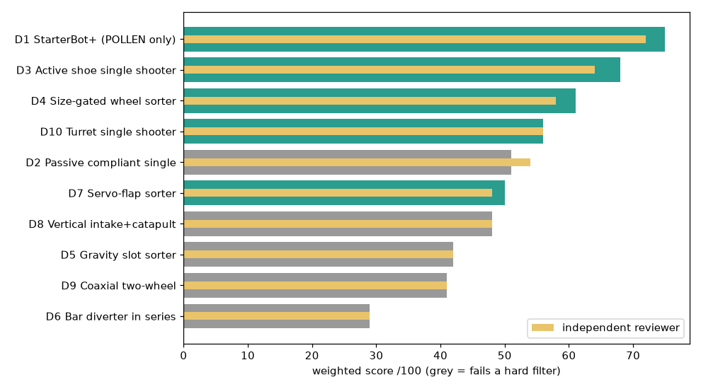
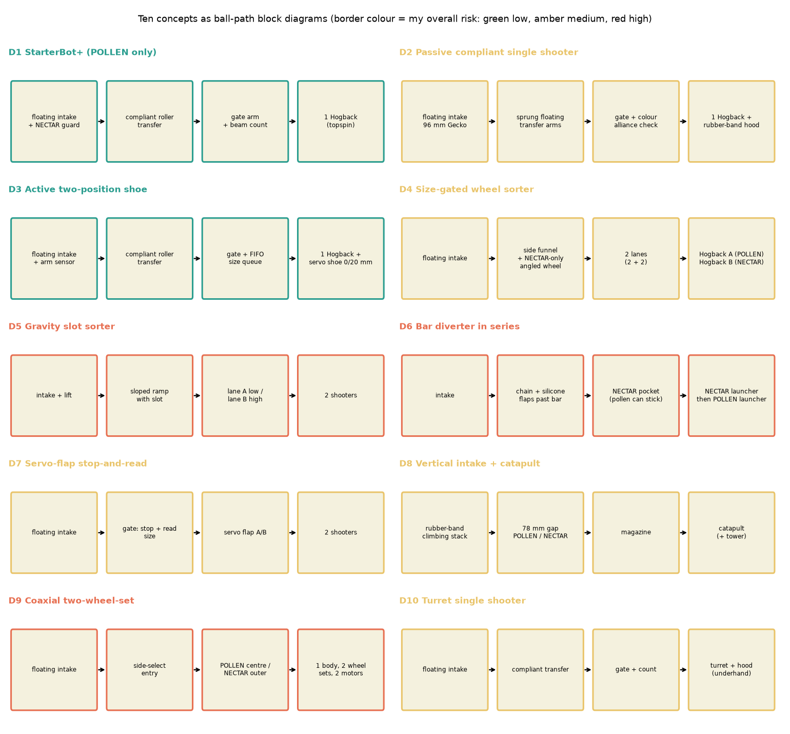
concept                            mine  reviewer  filters
D1 StarterBot+ (POLLEN only)        75.0    72   pass
D3 Active shoe single shooter       68.0    64   pass
D4 Size-gated wheel sorter          61.0    58   pass
D10 Turret single shooter           56.0    56   pass
D2 Passive compliant single         51.0    54   F2?
D7 Servo-flap sorter                50.0    48   pass
D8 Vertical intake+catapult         48.0    48   F3
D5 Gravity slot sorter              42.0    42   F3
D9 Coaxial two-wheel                41.0    41   F2
D6 Bar diverter in series           29.0    29   F2

Sensitivity of D1 vs D3 vs D4 to the NECTAR weight (C2), others scaled
 C2= 5  D1 81.5  D3 68.9  D4 58.8  D10 55.5
 C2=15  D1 75.0  D3 68.0  D4 61.0  D10 56.0
 C2=25  D1 68.5  D3 67.1  D4 63.2  D10 56.5
 C2=35  D1 62.1  D3 66.1  D4 65.5  D10 56.9
 C2=45  D1 55.6  D3 65.2  D4 67.7  D10 57.4
Shot physics
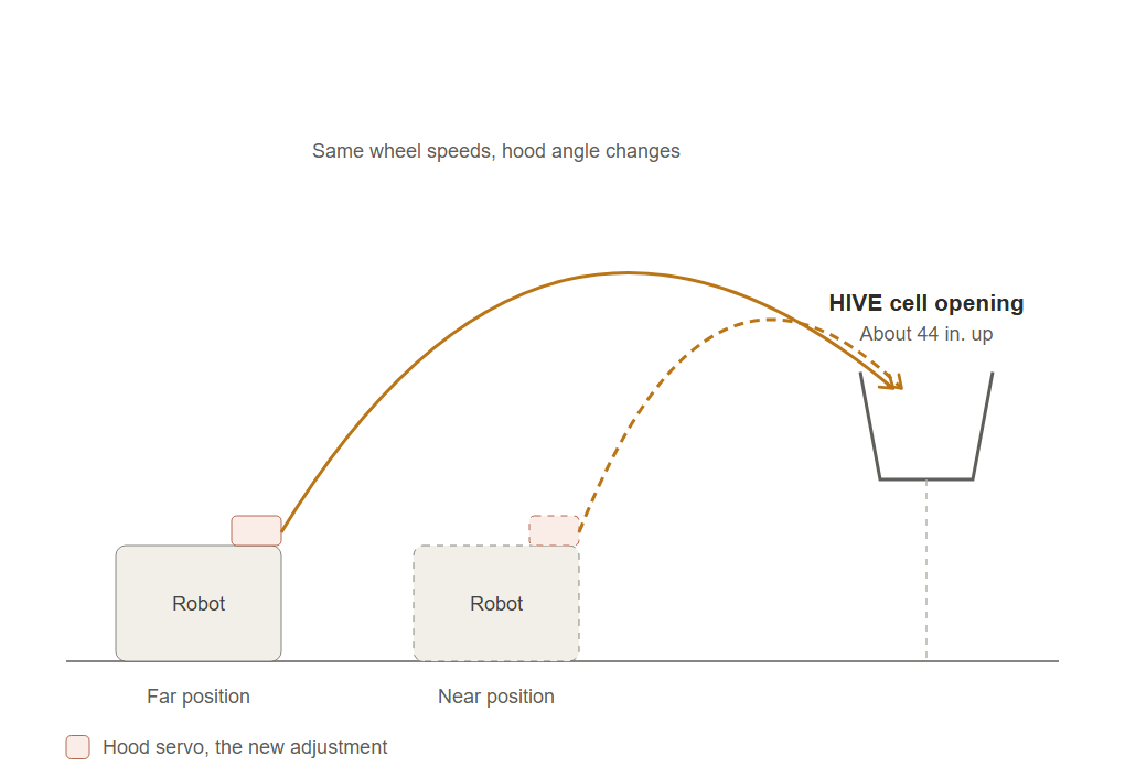
exit speed needed (m/s) to hit window centre; launch h0=0.37 m, target z=1.50 m
dist(m)  45deg  50deg  60deg  70deg
 1.0    nan   13.9    5.7    5.1
 1.5    7.7    6.4    5.5    5.6
 2.0    6.7    6.2    5.8    6.2
 2.5    6.7    6.3    6.2    6.8
 3.0    6.9    6.6    6.6    7.3
 3.5    7.1    6.9    7.0    7.8
 4.0    7.4    7.2    7.4    8.2

wheel rpm needed for k=0.5 / 0.6 at 50 deg:
 x=1.5 v=6.4  rpm(k=.5)=2536  rpm(k=.6)=2113
 x=2.5 v=6.3  rpm(k=.5)=2520  rpm(k=.6)=2100
 x=3.5 v=6.9  rpm(k=.5)=2751  rpm(k=.6)=2293

I=1.5e-04 kg m2 (stock Hogback ~120 g)
  x=2.0 POLLEN ball KE 0.66 J  wheel KE 4.9 J  -> speed drop 7.0% per shot
  x=2.0 NECTAR ball KE 1.09 J  wheel KE 4.9 J  -> speed drop 11.7% per shot
  x=3.0 POLLEN ball KE 0.76 J  wheel KE 5.7 J  -> speed drop 7.0% per shot
  x=3.0 NECTAR ball KE 1.25 J  wheel KE 5.7 J  -> speed drop 11.7% per shot

I=3.0e-04 kg m2 (+ 150 g masses)
  x=2.0 POLLEN ball KE 0.66 J  wheel KE 9.9 J  -> speed drop 3.4% per shot
  x=2.0 NECTAR ball KE 1.09 J  wheel KE 9.9 J  -> speed drop 5.7% per shot
  x=3.0 POLLEN ball KE 0.76 J  wheel KE 11.4 J  -> speed drop 3.4% per shot
  x=3.0 NECTAR ball KE 1.25 J  wheel KE 11.4 J  -> speed drop 5.7% per shot

I=4.5e-04 kg m2 (+ 300 g masses)
  x=2.0 POLLEN ball KE 0.66 J  wheel KE 14.8 J  -> speed drop 2.3% per shot
  x=2.0 NECTAR ball KE 1.09 J  wheel KE 14.8 J  -> speed drop 3.7% per shot
  x=3.0 POLLEN ball KE 0.76 J  wheel KE 17.1 J  -> speed drop 2.3% per shot
  x=3.0 NECTAR ball KE 1.25 J  wheel KE 17.1 J  -> speed drop 3.7% per shot
Match model
mean tips per 150 s for ONE robot (shared HIVE ignored)
D1 StarterBot+ (POLLEN only)             3.48
D2 passive single shooter                3.00
D3 active two-position hood              3.45
D4 size-gated wheel sorter, 2 lanes      3.16
D5 gravity slot sorter                   2.86
D6 bar diverter, launchers in series     2.50
D7 servo flap sorter                     3.06
D8 vertical intake + catapult            2.77
D9 coaxial two-wheel shooter             2.79
D10 turret single shooter                3.84

Sensitivity of a both-size design (p_nectar=p_pollen-0.03, shoot 3.5 s, collect 8.5 s):
D1 baseline 3.48
jam 0.05  p_pollen .60/.70/.80/.85 -> 2.54 3.08 3.60 3.88
jam 0.10  p_pollen .60/.70/.80/.85 -> 2.45 2.98 3.48 3.75
jam 0.20  p_pollen .60/.70/.80/.85 -> 2.28 2.78 3.25 3.48
jam 0.30  p_pollen .60/.70/.80/.85 -> 2.15 2.62 3.07 3.29

Value of NECTAR alone: same design with nectar disabled vs enabled (p_pollen .80, jam .10)
POLLEN-only 3.12   both 3.48   gain 12%
Match model, robustness
Robustness: random +/- perturbation of every design parameter (N=300)
D10 turret single shooter                mean rank 2.10   wins 142
D3 active two-position hood              mean rank 3.06   wins 49
D1 StarterBot+ (POLLEN only)             mean rank 3.12   wins 70
D4 size-gated wheel sorter, 2 lanes      mean rank 4.86   wins 18
D7 servo flap sorter                     mean rank 5.85   wins 8
D2 passive single shooter                mean rank 5.86   wins 5
D5 gravity slot sorter                   mean rank 6.65   wins 3
D9 coaxial two-wheel shooter             mean rank 7.18   wins 2
D8 vertical intake + catapult            mean rank 7.57   wins 3
D6 bar diverter, launchers in series     mean rank 8.75   wins 0
V4 carriage strength study (FEA)
Von Mises stress, displacement and safety factor for the V4 carriage plate.
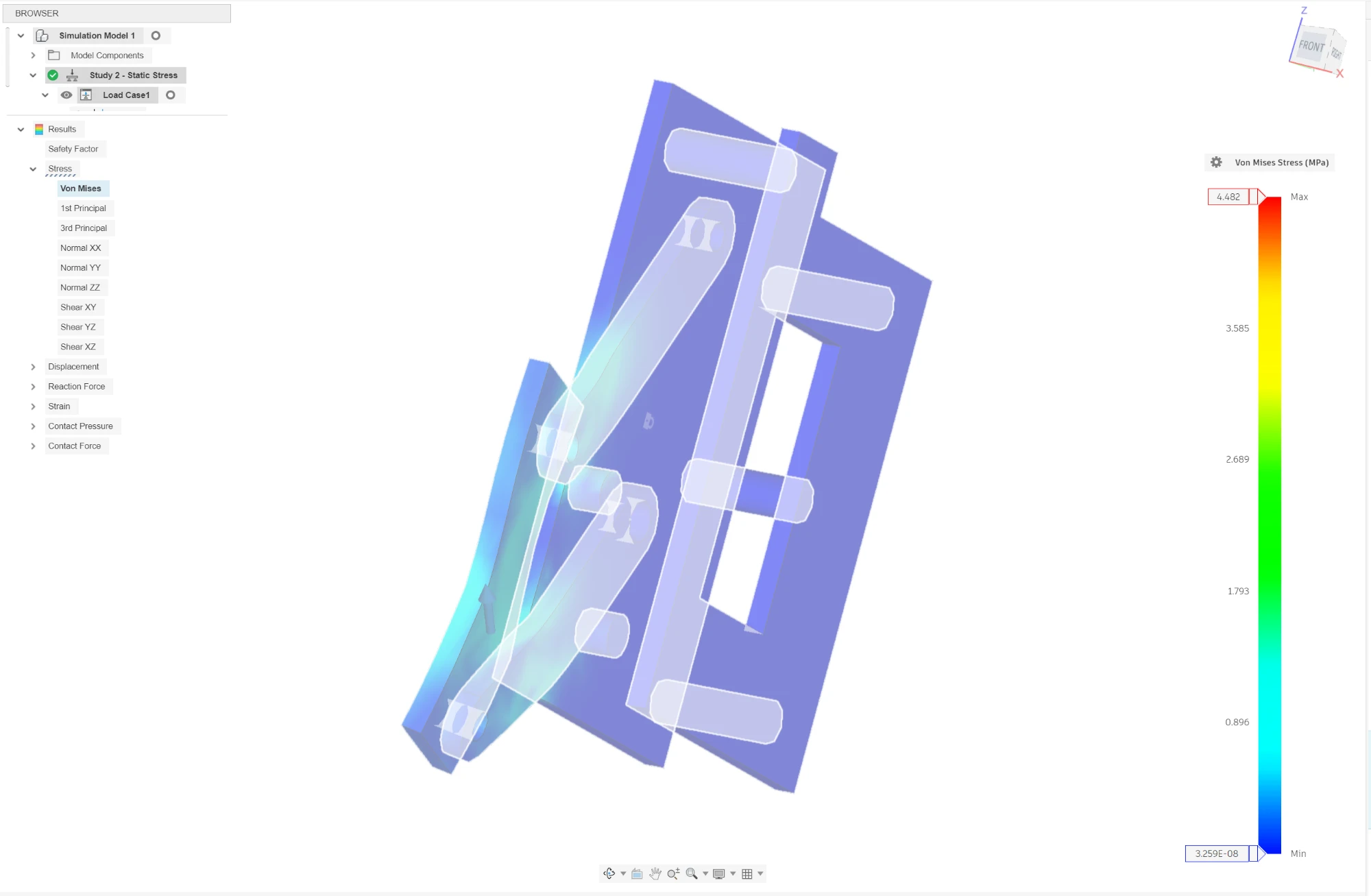
V4 progress and carriage finding
# V4: jointed carriage built (2026-11-02)

Fusion doc `BIOBUZZ StarterBot V4 (D3 carriage)` (copy of V3; V3 untouched). Images: `images/v4_side_stock_pose.png`, `images/v4_side_NECTAR_pose.png` (view from +x, Fusion's "right" view).

## What was wrong in V3
The hidden NECTAR-pose copies were never checked against the frame. Checked now, they collide:
- Block 1120-0002-0072 and motor 5203-2402-0019 run into the shelf bar `1121-0005-0144` that the wheel group hangs from (4 screws 2800-0004-0010:55-58 join them).
- The bar's front end, once moved, also runs into the big hood plate `1117-0216-0352 (_H)` (0.24 cm3 at the NECTAR pose, 0.07 at mid travel). The zip tie `2909-0101-0100 (_C)` that tied that bar end to the plate is hidden.
So the V3 NECTAR pose was not a valid pose. It is replaced by the V4 carriage below. The hidden V3 pose copies stay hidden in a reference group.

## What V4 now contains
- **Carriage** = wheel group (Hogback 3626-0014-0096, hub 1310-0016-4008, motor 5203-2402-0019 (4), block 1120-0002-0072, bracket 1201-0043-0002:7, two 100 g discs) + shelf bar (a copy of 1121-0005-0144 **cut to y > -30**, the stock bar is unchanged elsewhere) + carriage plate + the 20 screws that only join those parts (2801-0004-0008:13-16, 2800-0004-0012:24-31, 2812-0004-0007:36-39, 2800-0004-0010:55-58). One rigid group, `RG Carriage`.
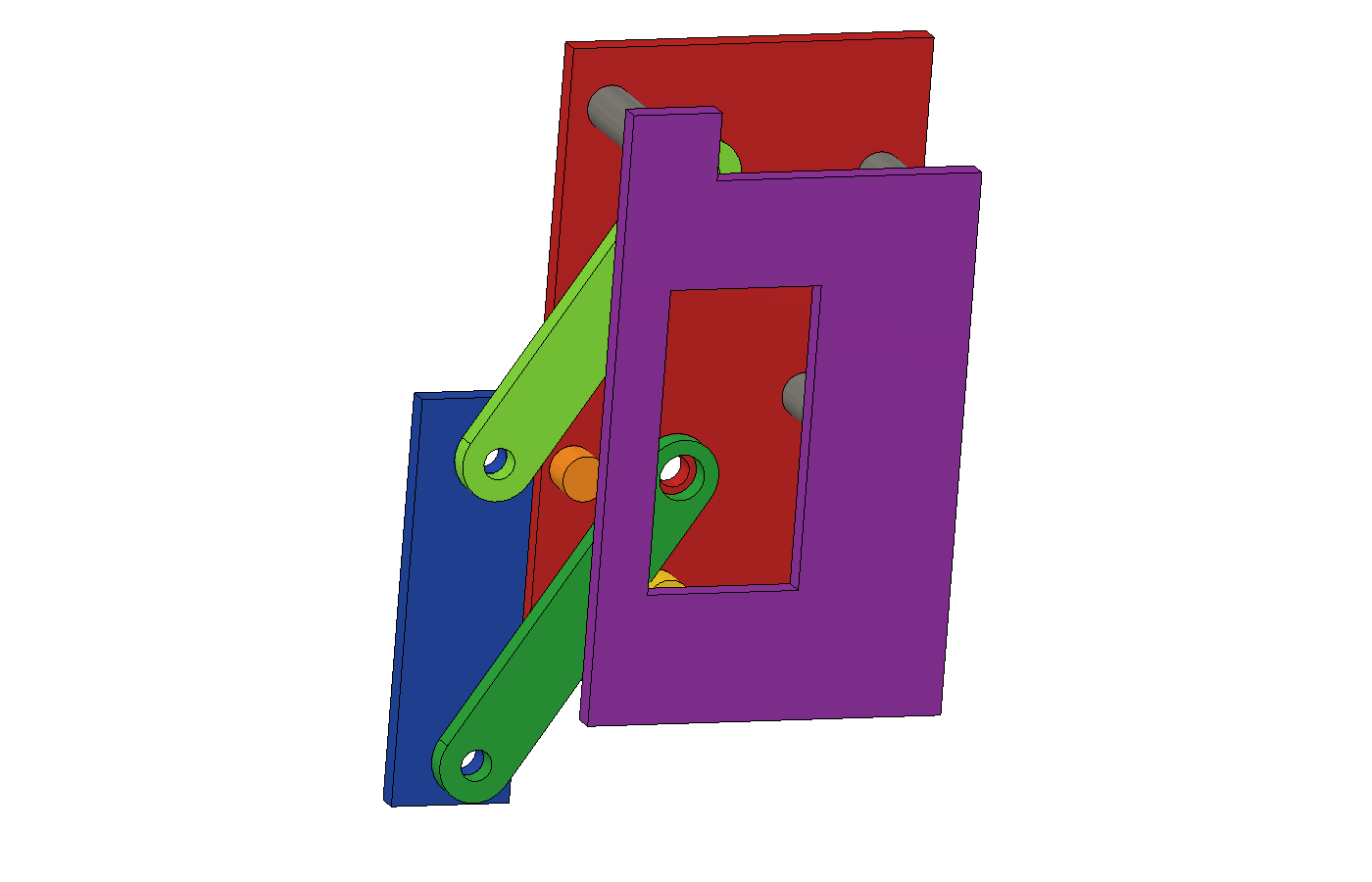
- **Ground plate** (x 92..95, y 66..112, z 170..244, 3 mm) on the channel's +x face, grounded.
- **Carriage plate** (x 92..95, y 46..62, z 144..198) on the bar's +x face.
- **Two links** (45 mm pin to pin, x 95..98), pins 40 mm apart on both plates: a parallelogram.
- **Four revolute joints** on the pins. Stops: ground joints -26.3..0 deg, carriage joints 0..+26.3 deg.
- Static frame and hardware: rigid group `RG Frame and static hardware` (1,624 members), chassis plate `1117-0088-0352 (_G)` grounded. Removed: 8 screws that tied block/motor to the channel (2800-0004-0010:69-72, 2812-0004-0007:32-35), hidden not deleted.
- Moved: the 3 spacers 1501-0006-0430 and their 6 screws are static (they do not touch the wheel group; V3 had them in the moving copy by mistake).

## What the model shows (read from Fusion)
- Drive ground joints to -26.3 deg (carriage joints +26.3): the carriage plate goes from (y 46.0, z 144.0) to (32.02, 158.96) = 14 back, 15 up, **orientation unchanged**. That is the V3 stock to NECTAR vector.
- Mid travel sags 1.2 mm off the straight line (arc of a 45 mm link); the end poses are exact.
- Interference (Fusion interference analysis, carriage parts against every visible static part, bounding-box candidates, 5 poses 0, -6.5, -13, -19.7, -26.3 deg): **0 clashes**. A control pose at +8 deg (bar driven into the channel) was detected, so the check works.
- Pose drives only work by setting all four joints (ground joints t, carriage joints -t) because the loop is closed.

## Numbers that matter
- **Carriage mass is about 0.99 kg**, not 0.4 kg: motor 503 g, Hogback 81 g, hub 56 g, block 51 g, bracket 17 g, discs 202 g, bar 32 g, plate 20 g, links 24 g (Fusion masses; the motor figure is not verified against goBILDA's spec). Plus about 40 g of screws. Doc 15's 0.4 kg was low.
- Hold force along the travel: gravity 7.4 N (up component 0.73) plus the shot reaction. The reaction is **unmeasured**; at an assumed 30 N peak the carriage needs about 37 N, i.e. 1.7 N m (17 kg cm) at the link pivots with a direct-drive servo, before any gearing.
- The shot reaction pushes the wheel away from the ramp, toward the NECTAR pose. In the NECTAR pose the far stop carries it. In the stock (POLLEN) pose nothing does except the servo, so it needs a **spring preload or a latch toward the ramp** that is larger than the reaction. Spring and servo are not modelled.

## Servo, stops and the spring question (added later the same day)
Images: `images/v4_servo_iso_stock_pose.png`, `images/v4_servo_iso_NECTAR_pose.png`.

**Built in V4**
- A goBILDA 2000-series servo (the CAD file is the 25-3 Speed housing already in the model; the 25-2 Torque is the same size class but I did not check its drawing) sits on the +x side with its 25-tooth spline in a 6.1 mm hole in link A, on the pivot axis. Direct drive. Case 40 x 20 mm in a 40.5 x 20.4 mm pocket in a 3 mm bracket plate (x 112.1..115.1) on four 6 mm posts from the ground plate. The servo's own case screws sit inside the pocket; the ear screws that hold it to the bracket are not modelled.
- Ground plate extended to y 63 and z 160 to carry the stops. Two 6 mm hard-stop posts on the ground plate, one at each end of link A's swing (POLLEN end and NECTAR end). They carry the load, not the servo.
- Interference over the whole travel (0, -6.5, -13, -19.7, -26.3 deg): new parts against all static and moving parts, **0 clashes** except the intended contacts: link A touching its two stops (about 1 mm3 of overlap each, a contact), and the spline in its hole (0.0001 cm3).
- One post (post 4) moved to y 68.5 / z 236 because it clipped link B at the NECTAR end.

**Why no spring** (hand calculation, assumptions stated)
- Lever from the link pivot to the carriage's line of travel is 43.8 mm at both ends, 45 mm at mid. So force along travel F = torque / 0.0438 m.
- Gravity along travel: 7.4 N (1.03 kg, up component 0.73). It pushes the carriage into the POLLEN stop and away from the NECTAR stop.
- The shot reaction R (unmeasured) pushes the carriage away from the ramp, toward the NECTAR end. At the NECTAR end the stop takes it. At the POLLEN end only the servo resists R minus gravity.
- A spring toward the POLLEN end would hold R there, but then the servo has to hold the spring plus gravity at the NECTAR end. For R = 30 N that is more than 30 N at the NECTAR end, no better than holding R at the POLLEN end. A spring just moves the load to the other pose and makes it worse across the stroke, so none is modelled. A toggle or a latch that carries R mechanically is the real alternative.
- goBILDA stall torque (listed on gobilda.com): 25-2 Torque 17.2 / 21.6 / 25.2 kg cm at 4.8 / 6.0 / 7.4 V; 25-3 Speed 7.9 / 9.3 / 10.8 kg cm. At the 43.8 mm lever, stall holds 55 N (Torque, 7.4 V), 47 N (Torque, 6 V), 24 N (Speed, 7.4 V), 20 N (Speed, 6 V).
- Hold needed at the POLLEN end = R - 7.4 N. For R = 30 N that is 22.6 N = 10 kg cm. The Speed servo that is in the model cannot do it with margin; the **Torque servo (25-2) at 6 V or 7.4 V holds it with 2x margin**. Holding at NECTAR needs only gravity (7.4 N, 3.3 kg cm).
- If the measured R is above about 40 N, the servo is not enough: add a toggle linkage or a latch. That needs a ground anchor ahead of the carriage that the current frame does not have (the hood plate H is a thin curved flexible sheet, not an anchor).

## Strength check (2026-11-02, hand calculation; Simulation study not run)
Fusion answers again, but `adsk.sim.Simulations.get` returns nothing for this 1,814-occurrence document and the Simulation workspace shows no model, so no Static Stress study was run. Not a finding about the design. Hand check instead, **assumes 6061 aluminium (yield about 276 MPa); the Fusion parts carry no verified material, so confirm what is cut/printed**.
- Loads: 25, 40, 60 N along the travel line, shared by two links (30 N each at 60 N); servo stall reaction 2.5 N m at 7.4 V.
- Link, section at the pin hole (3 mm x (10 - 4 mm)): about 2 MPa at 30 N. Hole bearing (3 x 4 mm): about 3 MPa.
- Stop post (r3, 5 mm long) at 60 N: shear about 2 MPa, bending under 20 MPa.
- Servo bracket (3 mm, 40 mm wide) carrying the 2.5 N m reaction on four posts: about 30 MPa bending. Safety factor about 9 in aluminium; **about 1.6 if it were printed PLA**, so cut it from metal or thicken it.
- Everything else is under 5 MPa. Stiffness (deflection) is not covered; a measured deflection under the bench load is the check for that.

Study file: `V4 carriage strength study` (project 20789 - PAOS), 11 parts copied from V4 in the stock pose with 6061 aluminium assigned (ground plate, carriage plate, links A/B, two stop posts, servo bracket, four servo posts). STEP copies in `sim_study/`. Scripting still cannot create the study, so it is set up by hand in the Simulation workspace.

## Fusion Static Stress result (2026-11-02, study file `V4 carriage strength study`, Study 2)
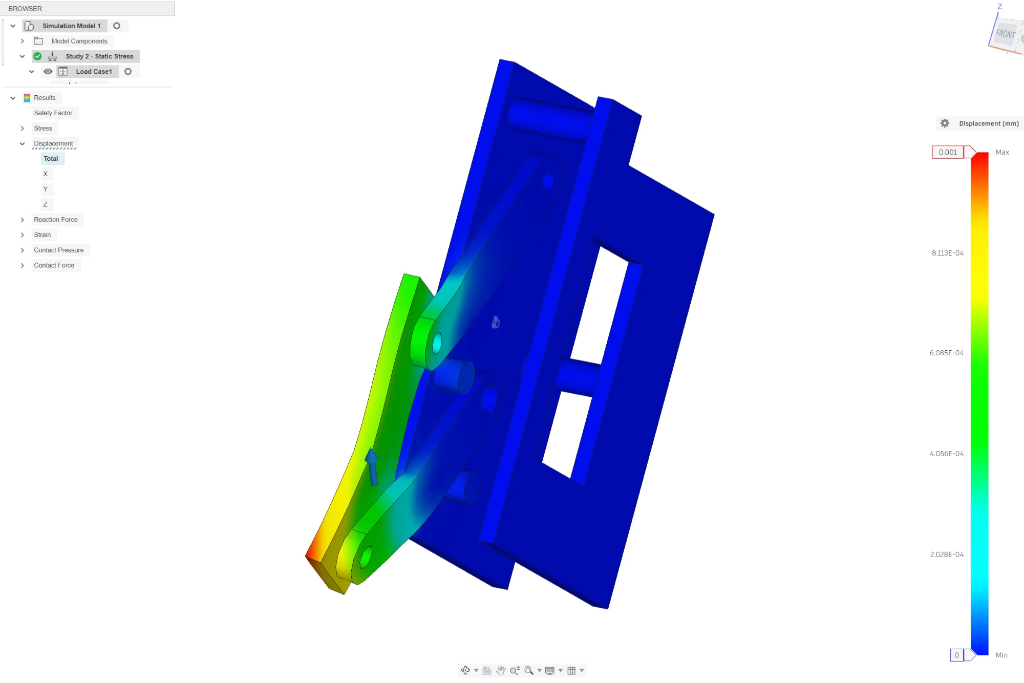
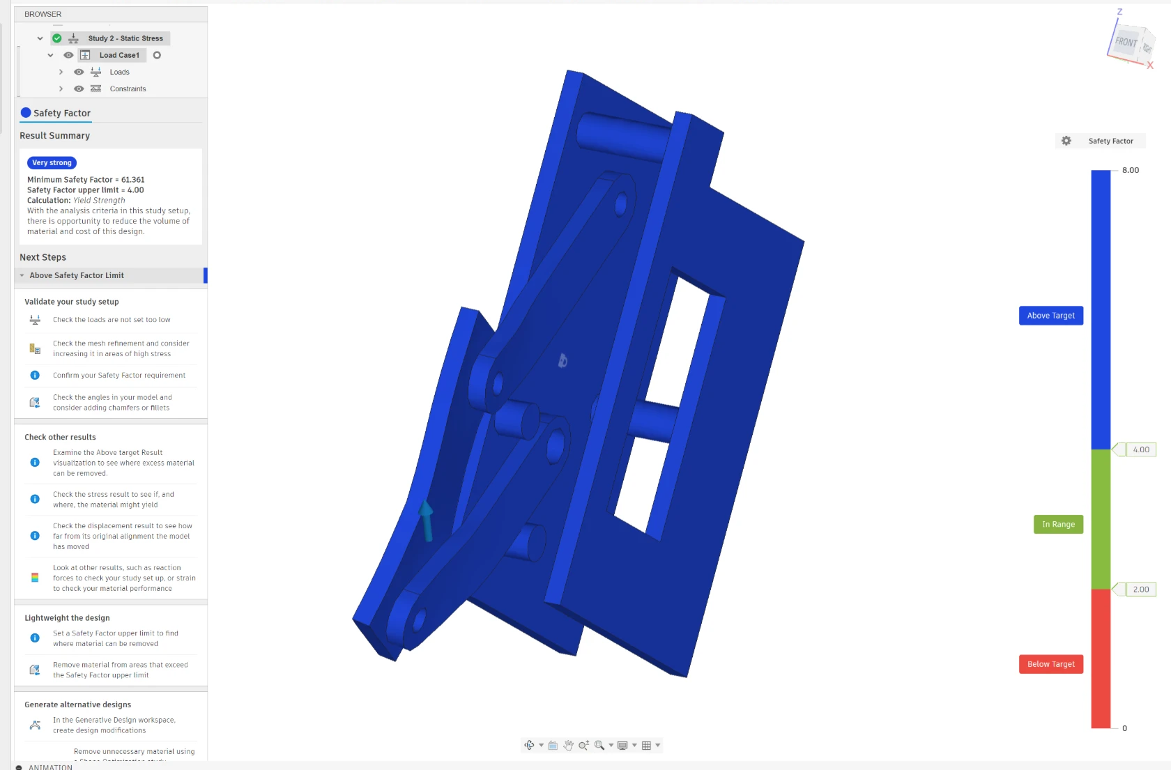
Scripting could not reach Simulation, so Mark set it up in the UI from the labelled parts: aluminium 6061, ground plate back face fixed, force on the carriage plate back face (60 N case: Y -40.9, Z +43.9 N), automatic bonded contacts (0.10 mm), default mesh, solved on the cloud for 0 credits. Pre-check clean.
- Max von Mises stress **4.48 MPa** (yield 276 MPa).
- Minimum safety factor **61.4** ("Very strong").
- Max displacement **0.001 mm**, at the free end of the carriage plate.
- Agrees with the hand check (under 20 MPa). Only the 60 N case was run; 25 and 40 N are lower loads on the same model.
- Limits: contacts bond the whole touching faces, not pins, so the carriage is stiffer than the real pinned joint and hole-edge stress is understated (hand check: about 3 MPa bearing); the shot load is Y/Z along travel only; linear study, no yielding or buckling.
- Bracket check: the 2.5 N m servo stall torque was not applied in Fusion; the hand number (about 30 MPa, safety factor about 9 in aluminium, about 1.6 in PLA) stands.

## Still not done
1. Measured shot reaction R (bench), ear screws for the servo, and the 25-2 housing check. (Servo, stops and bracket are now modelled; spring rejected as above; latch or toggle only if R > about 40 N.)
2. Fasteners between the carriage plate/bar and the ground plate and channel: modelled as plates only; hole positions not matched to the goBILDA hole grid yet.
3. Pins are not modelled as parts (joints sit on sketch points).
4. Tie C and the stock bar (:2) are gone from the model; other zip ties near the hood unchecked.
5. Ball bodies carry default density (POLLEN 1,479 g, NECTAR 3,143 g): fix before a mass or centre-of-gravity study.
6. Colour sensor, beam pair, intake stand-off change, 96 mm Gecko: not in V4 yet.
7. Simulation workspace: not tried (Student licence shown, no extension listed). Not needed for the checks above.

## Ball gate, first pass (2026-11-02)
- Cleanup: hidden V3 NECTAR-pose copies deleted (motor, block, bracket, hub screws, 3 spacers, balls, discs, 8 screws, tie C); flywheel discs kept. V4 unsaved.
- My first gate (a 6 mm stop bar at y 81.6 / z 55.2) was built and then REMOVED: it floated, and it was placed from the V3 "hold" ball, whose position is wrong. Checked by interference: the V3 hold ball overlaps the feed roller by 4.6 cm3 (roller centre y 85, z -14, r 36; ball centre y 49.9, z 32.7, r 35.6; 58 mm apart, needs 71.6).
- Finding: V4 already has a feeder. A 72 mm wheel (3613-0014-0072:4, x -17..7, y 49..121, top at z 22) driven by a 2000-series servo (2000-0025-0003:3, x -62..-17) through beam 1805-0043-0001:1 and part 1910-0025-0812:1. A stopped feeder holds the ball against the ramp; spinning it feeds the wheel. That is the gate, as in the stock StarterBot.
- Open: whether a stopped roller holds a ball on the ramp slope (friction), the real resting positions of POLLEN and NECTAR (not the V3 "hold" ball), colour sensor position, NECTAR intake.

## Windmill restored (2026-11-02, Mark's correction)
- Mark: the stock windmill advances the balls AND gives a controlled place to read ball colour. V3 (doc 15) had removed it and put a roller feeder in its place; that dropped the colour-check role. Not removed in today's cleanup.
- Restored in V4 from clean V1 at the stock position (STEP copies in `sim_study/windmill_block.step`, `windmill_servo.step`): servo block with hub, vanes and screws (x -90..-46, y -62..6, z 76..107) and torque servo 2000-0025-0002 (x -78..-58, y -57..-3, z 85..129). Bounding boxes equal V1 exactly.
- Interference against the V4 frame: none. The 14 overlaps reported are inside the windmill itself (stock screws in the servo case, spline in hub, under 0.04 cm3).
- Not yet checked: NECTAR (91.4 mm) vs the stock vane pockets (sized for POLLEN, doc 02 says verify); whether the lane left wall, moved 12 mm out in V3, still lets the vane tips reach the ball; the V3 roller feeder now duplicates the windmill's job (decide after bench).
- Colour sensor goes at the windmill pocket, looking at the held ball; part not placed yet.

## Validation pass and animations (2026-11-02)
File: `animations/biobuzz_animations.html` (three scenes: collect/move/shoot, camera tracks the HIVE, shot arcs by distance). Dimensions from the V4 model; assumed paths dashed.
- Shot speed (fixed 50 deg ramp, exit 0.19 m, aim 1.15 m): 5.7 m/s at 2 m to 7.1 m/s at 4 m, wheel 2,300 to 2,800 rpm (ball speed taken as half the wheel surface speed). Matches the research range. Under 2 m the ball is still rising when it reaches the window (reachable, less forgiving; test).
- Heading tolerance to a 20 in window: +/-6.2 deg at 2 m straight on, +/-3.0 deg at 4 m, +/-1.9 to 2.1 deg at 4 m and 45 deg off axis (NECTAR smaller). Heading lock must hold under 2 deg.
- Camera (C920 70 deg wide, about 43 deg tall, lens about 0.38 m above floor, tags assumed 1.1 m): tags sit 10 to 36 deg above level from 4 to 1 m, so tilt the camera up about 15 deg. Tag placement on the cell underside still needs a field check.
- Field geometry: hive is at the field centre, so from a wall the straight-on range is about 1.5 m; from a corner about 2.1 m.
- Model conflict: V3 hold ball overlaps the feeder roller by 4.6 cm3; roller feeder duplicates the restored windmill. Floor-to-deck climb unproven.
- Still open: NECTAR vs windmill vane pockets, colour sensor part and mount, intake float change for NECTAR, shot reaction R, servo gate/latch decision.
- Correction (same day, Mark's question on scene 3): earlier speeds ignored air drag. With drag (Cd 0.47, 25 g / 41 g balls): launch 6.0 m/s at 2 m, 6.8 at 3 m, 7.65 at 4 m, the same for both balls (area/mass 0.159 vs 0.160). Using the no-drag speeds would miss low by 0.33 m at 3 m. Wheel rpm per ball is an estimate only; calibrate on the bench.

## Rulebook check and corrections (TU07, 2026-11-02)
- HIVE opening is 1.36 to 1.67 m above tiles (53.5 to 65.6 in, Fig 9-10), tilted 30 deg, 20 in wide, 14 in tall, 12 in deep; centre about 1.51 m. My earlier aim height of 1.15 m was wrong. Redone with drag: launch 7.0 m/s at 2.2 m, 7.3 at 3 m, 8.0 at 4 m (wheel about 2,800 to 3,200 rpm, estimate), same for both balls. Ball is still RISING at the opening under about 2.2 m (7.8 m/s at 1.5 m), so shoot from 2.2 m or more or add a steeper ramp.
- AprilTags (sec 9.9, Fig 9-16): 3.25 in tags, one 4-tag cluster on the BOTTOM of each CELL, facing down. A camera 0.4 m high sees them at a grazing angle: at 720p under 2 px per tag module beyond 2 m; 1080p gives about 2 to 4 px out to 2 m. So odometry (Pinpoint) is the primary range/bearing source; the camera corrects at close range. Limelight 3A is the alternative; its field of view is narrower (higher px per metre) but the grazing angle is the same.
- Balls: POLLEN yellow 71 mm, NECTAR red and blue 91 mm, "not perfectly spherical", so the colour sensor must separate yellow, red, blue. G408 means only own-colour NECTAR.
- Shot reaction on the carriage (computed, not measured; 7.3 m/s, 25 g and 41 g balls, ball driven over 60 to 100 mm, friction 0.5 to 0.8, peak = 2 x average): normal load on the wheel 8 to 22 N average and 17 to 44 N peak for POLLEN; 14 to 36 N average and 27 to 73 N peak for NECTAR. The push runs almost exactly along the carriage travel (cosine 0.99). At the POLLEN end the servo must hold the peak minus 7.4 N gravity: up to about 37 N against 47 N (6 V) or 55 N (7.4 V) available, so margin is only 1.3 to 1.5 at the worst case and the doc 17 rule (over 40 N: latch or toggle) is close. Likely fine at the friction 0.8 and 100 mm end of the range, not fine at 0.5 and 60 mm. At the NECTAR end the hard stop takes it; 73 N is still inside the Fusion study (60 N gave safety factor 61). Decision: keep the torque servo, run bench test 17 first, add a latch only if the measured peak is over about 40 N at the POLLEN end.
- Windmill contact: deck is G plate at z -14 (y -70 to -15), so a POLLEN on the deck tops out at z about 57 and a NECTAR at about 77. The restored windmill vanes sit at z 82 to 99. They clear both balls by 5 to 25 mm and cannot push them. Either the stock mount height differs from the V1 CAD or the vanes work on a ball sitting higher. UNRESOLVED; needs the physical robot.

## Stock V1 check of the windmill height (2026-11-03)

Opened the saved "BIOBUZZ StarterBot V1" (the unmodified goBILDA 3200-2627-0004 import, read only, not saved) and measured it directly. Nothing in V4 had moved the windmill; the stock numbers are identical.

| Item (stock V1) | Measured |
|---|---|
| Windmill vanes (4x Small Gridplate A, part 1805-0043-0001) | z 82..99, x -90..-46, y -62..6 |
| Windmill servo and ServoBlock | z 76..129 (above the vanes) |
| Deck under the windmill (plate 1117-0088-0352 _E, x -130..133, y -100..-12) | top surface z -17 to -18 |
| POLLEN (71.1 mm) sitting on that deck | top at z 54 (28 mm below the vanes) |
| NECTAR (91.4 mm) sitting on that deck | top at z 74 (8 mm below the vanes) |

Assembly guide steps 52-56 (pages 32-33) build the windmill on a Quad Block Mount hung from a 5-Hole Low Channel at the top of the left upright, which matches the CAD height. So the stock CAD, built exactly per the guide, has the vanes above the ball on the deck. A guide-conforming build will not push a ball sitting on the deck. The guide does not say what the windmill acts on, and the stock robot is not built, so there is nothing to confirm on hardware yet.

Decision for V4 (WITHDRAWN, see "Windmill height RESOLVED" below): do not copy the stock height. Lower the windmill so the vanes sit at the ball equator (POLLEN centre z about 18, NECTAR about 29, so vane band roughly z 5..45). That is a model change still to make and check against the intake and the deck lip.

### Windmill height RESOLVED from stock V1 geometry (2026-11-03, after Mark's hint)

Mark: the vanes are probably not too high (front rollers flick balls up), and a lower windmill would hit the chassis. The stock V1 bounding boxes support both points. Four 1117-0040-0352 wall plates stand z 32..73 around the windmill: x -91..-89 (y -116..-20), y -63..-61 (x -88..8), x -47..-45 (y -60..36), y -19..-17 (x -144..-48). They form a pocket about 41 x 42 mm (x -88..-47, y -61..-19) with its rim at z 73, 90 mm above the deck, directly under the vanes (z 82..99).

A ball cannot fit in the 41 mm pocket, so it rests on the rim. Pocket half-width a = 20.5 mm (corner 29 mm):
- POLLEN (r 35.5): centre z = 73 + sqrt(35.5^2 - 20.5^2) = about 102, so the vanes (z 82..99) meet it just below its equator.
- NECTAR (r 45.7): centre z = 73 + sqrt(45.7^2 - 20.5^2) = about 114, so the vanes meet the lower half, 15..32 mm below centre.

So the stock vane height is correct for a ball sitting in the pocket, and lowering the windmill would hit the walls. The earlier "move the windmill down" decision is withdrawn. Remaining check: the ball must be lofted from the deck (z -17) to the rim (z 73), which the front rollers do in the stock design; not yet modelled.

### CORRECTION 2026-11-03 (supersedes both windmill sections above): the vanes are the four plates, not the bracket at z 82..99

Exporting the stock V1 meshes showed that the part I called "vanes" (1805-0043-0001, z 82..99) is the Quad Block Mount, the bracket on the servo. The guide's "four Small Gridplate A" (step 53) are the four 1117-0040-0352 pieces _A:1..:4, which stand z 32..73 and are 96 x 40 mm each. They sit in a pinwheel around the servo axis (x -68, y -40): A:1 at x -90 (y -116..-20), A:2 at y -62 (x -88..8), A:3 at x -46 (y -60..36), A:4 at y -18 (x -144..-48). Each is the 90-degree rotation of the next about the axis. So the windmill vanes DO reach ball height: bottom z 32, top z 73, against POLLEN z -17..54 and NECTAR z -17..74 on the deck. The earlier "vanes too high" finding and the "ball rests on the pocket rim" resolution were both wrong. Plate A:2 (y -62, x -88..8) stands across the entry lane, so the windmill is also the gate in front of the ramp. The 5-hole low channel (1201-0043-0002:8, z 64..77) is the hub bar.

How the intake is built (from the same meshes): seven 48 mm compliance wheels (3613-4008-0048, x -101..83, axis along x, centre y -185 z 36), then a 16-ring 18 mm tube roller (3618-4008-0016, axis x, centre y -128 z -8, x -128..128), then the deck plate E (y -100..-12, top z -17).

## Stock V1 ball-flow model (2026-11-03): what is established

Tooling (in `sim_study/`): `flow_v1_stl/` holds the stock V1 parts exported from Fusion with their transforms; `flow_load.py` loads them in world mm; `flow_clearance.py` finds the route that minimises the worst interpenetration of a rigid ball through the CAD; `flow_swing.py` and `flow_lift.py` repeat that with the gecko module moved; `flow_model.py` is a MuJoCo ball/robot model (hull-cell collision from the real meshes, moving gecko wheels, roller, flywheel and windmill). Python venv is `sim_study/venv`.

Source facts from goBILDA's own overview video "FTC Starter Bot Overview (BIOBUZZ)" (Ethan, goBILDA, transcript read 2026-11-03):
- The stock robot is built for POLLEN only; goBILDA says it is "not designed to launch the nectar".
- Intake: seven 48 mm Gecko wheels plus two 72 mm Gecko wheels (the 72 mm ones pull from corners and out of the FLOWER). POLLEN is "popped up over" the 8 mm REX shaft that carries the 16 mm rubber intake rollers. Those rollers do NOT roll; they are a fixed rubber back stop that gives the 48 mm wheels grip to pull the ball up inside.
- The intake can pivot and float up and down a little, limited by standoffs; that limit is why it cannot take NECTAR.
- The hopper holds up to four POLLEN. One torque servo drives the windmill, a set of polycarbonate grid plates, which actively pulls POLLEN into the 96 mm Hogback (6,000 rpm motor) and stops balls entering the wheel while driving.
- goBILDA expects teams to improve the windmill first because a ball not fully constrained can fail to be pulled in.

What the CAD shows, measured on the exported meshes:
- The tube roller is a FIXED bar (so my first model, a free-spinning roller, was wrong). Gecko wheel centre (y -185, z 36, r 24) to roller centre (y -128, z -8, r 8.5) leaves a 39.5 mm throat in the nominal pose. POLLEN is 71.1 mm, NECTAR 91.4 mm. With rigid balls nothing gets through until the module floats.
- Float pivot, taken from the 80 mm shafts' bearings in the side U-channels: axis along x at y -144, z 48. Rotating the gecko module about it, the worst unavoidable interpenetration for a rigid ball is: 0 deg 16.5 mm POLLEN / 26.6 NECTAR; 20 deg (front up 15 mm) 10.8 / 21.0; 40 deg (front up 29 mm) 7.7 / 17.9. The ball and the rubber wheels have to give the rest. The swing limit set by the standoffs is NOT yet measured, so how much float the stock robot really has is open.
- The deck plate E (1117-0088-0352 _E) is tilted sideways: z = 0.18 x + 0.02 y - 13.2, about 10.3 degrees, rising toward +x. A ball on it rolls toward -x, toward the windmill (centre x -68, y -40) and the left wall. At x 0 the deck is at z -9, at x -70 it is -17. So the deck is a gravity feed into the windmill. The earlier "z -14 / -17" deck heights were single-point values.
- Plate G, the ramp, is flat at about z -10 from y -20 to y 10 and then curves up to z 156 at y 190.
- AndyMark am-5851/5852 balls are Gopher ResisDent polyethylene shells, stiff, so a 20-30 mm squeeze is not credible; the module float must provide the clearance.

Retracted: "the front roller spins and flicks the ball" (it is fixed), and the earlier deck/vane heights.

Not yet done: gecko wheel direction and speed (the guide implies the 50.9:1 motor through a 100T/20T pair; 5:1 up would be about 585 rpm, down about 23 rpm; unverified), the standoff stop angle, a dynamic run of POLLEN through the gecko, deck, windmill, ramp and flywheel with calibrated compliance, and the same for V4.

### goBILDA example code read (2026-11-03): `research/gobilda_example_code/x/BioBuzzStarterbotTeleopMecanum.java`

Downloaded from goBILDA with Mark's yes (4.8 kB, MIT licence, one file). What it fixes:
- The windmill servo is driven as a continuous-rotation servo (`CRServo`, direction REVERSE) at full power 1.0 while the right bumper is held AND the launcher velocity exceeds the minimum. It is not indexed in 90 degree steps. It stops (power 0) otherwise, which is what holds balls back while driving.
- Launcher target 1250 ticks/s = 2678 rpm (minimum 1200 = 2571 rpm), motor 1:1 on the 96 mm Hogback, so rim speed is about 13.5 m/s. Spin-up is required before the windmill runs.
- Intake: one motor on the Gecko shaft (power = right trigger minus left trigger, reverse available) and two CRServos on the 72 mm corner wheels, same sign (right one reversed in code so both pull in). While shooting, the intake gets +0.5 power to dislodge stuck balls.
- The code gives no rpm or ratio for the intake motor. The 50.9:1 motor is 117 rpm at the gearbox output; the gear train from the CAD is 100T/20T, direction not stated.
- There is no colour sensing in the stock code. Ball sorting by colour is not part of the stock design.

### Measured balls (Mark, 2026-11-03)
- Yellow POLLEN: 70 to 72.5 mm diameter, 25.2 g.
- Blue NECTAR: about 90 mm diameter, 40.3 g.
- Mark: the balls have holes and are not consistent (manufacturing variation), so keep the nominal sizes for design (POLLEN 71.1, NECTAR 91.4 per manual) and design for the spread. Squeeze, bounce and friction tests are deferred to Oliver.
- Model use: POLLEN design range 70 to 72.5, NECTAR 89 to 92 (manual nominal 91.4, measured about 90). Masses 25.2 g and 40.3 g replace 25 and 41.

## V4 vs V1 diff and windmill restore (2026-11-03)
- Compared all occurrences of V4 against V1 (sim_study/dump_V1.json, dump_V4.json). V4 had lost the four windmill vane plates (1117-0040-0352 _A:1-4), the hub bar (1201-0043-0002:8) and the windmill's loose hardware. The 11-02 "restore" copied only the servo block and bracket because the vanes were misidentified then.
- Restored in V4 (unsaved) from V1 STEP copies (sim_study/restore/): four vane plates and the hub bar, bounding boxes identical to V1. Components are named "WINDMILL RESTORED ...". Windmill screws and nuts (about 30 loose fasteners) were not restored. Bounding-box interference against the 88 new or moved V3/V4 parts: none (one 0.3 mm contact between hub bar and servo mount, same as stock).
- Other V4 differences are intentional: 14 parts moved 12 mm in -x (V3 lane widening), ramp G cut and patched, feeder Gecko and servo, carriage parts. One stray 2 mm pin body exists in the shared Screw component (cosmetic).
- Intake model findings (doc 19): a pod spring does not help (even 0.03 N m/deg kills POLLEN); a raised pod rest does not help; powering the bar does not help; lowering the bar helps: POLLEN enters with the bar 10 to 20 mm lower. NECTAR gets over the lowered bar but stops at y -108, blocked by the vane pocket walls (sized for POLLEN). So NECTAR needs both a lower bar and a wider pocket path; next step is to export V4 geometry into the model.
Flow model assumptions and results
# Ball-flow model: assumptions and first results (2026-11-03)

Files in `sim_study/`: `flow_params.py` (every input, with status), `flow_model2.py` (MuJoCo model built from the stock V1 CAD meshes), `flow_run.py` (scenario runner), `flow_clearance.py` / `flow_swing.py` (rigid-ball clearance), `flow_sweep1.py` (parameter sweep). To change an input, edit `flow_params_override.json` (name: value) or pass `params={...}`; nothing else needs touching. `python flow_params.py` prints the table below.

Status key: measured = Mark 2026-11-03; source = goBILDA video/code/CAD; assumed = placeholder until measured.

| name | value | unit | status | note |
|---|---|---|---|---|
| pollen_d_mm | 71.1 | mm | measured | 70 to 72.5 measured; manual nominal 71.1; holes make it vary |
| pollen_mass_g | 25.2 | g | measured | Mark 2026-11-03 |
| nectar_d_mm | 90.7 | mm | measured | about 90 measured; manual nominal 91.4 |
| nectar_mass_g | 40.3 | g | measured | Mark 2026-11-03 |
| ball_stiffness_N_per_mm | 6.0 | N/mm | assumed | force/deflection when squeezed between flat plates; test with Oliver |
| ball_damping_Ns_per_m | 3.0 | N s/m | assumed | damping of that squeeze |
| ball_mu_hard | 0.35 | - | assumed | ball on aluminium/polycarbonate sliding friction; incline test |
| ball_mu_floor | 0.7 | - | assumed | ball on field tile |
| ball_roll_resist | 0.0004 | m | assumed | rolling friction length scale |
| ball_restitution_note | not modelled | - | assumed | drop test pending; contact damping stands in for it |
| gecko_rpm | 585.0 | rpm | assumed | 117 rpm gearbox x 100T/20T speed-up if that is the gearing; 23 rpm if reduced |
| gecko_dir | 1 | +1 pulls ball rearward along the floor | assumed | CAD does not give direction |
| gecko_stiffness_N_per_mm | 3.0 | N/mm | assumed | rubber wheel radial stiffness |
| gecko_mu_ball | 1.2 | - | assumed | GripForce rubber on polyethylene |
| gecko_stall_torque_Nm | 2.0 | N m | assumed | per-wheel share at the gecko shaft; 50.9:1 YJ stall 3.6 N m x ratio / 7 wheels |
| roller_mu_ball | 0.9 | - | assumed | fixed rubber roller bar on ball (goBILDA: rubber back stop) |
| module_float_limit_deg | 30.0 | deg | assumed | swing allowed by the standoffs; unmeasured, robot not built |
| module_pivot_y_mm | -144.0 | mm | source | 80 mm shaft bearings in the side U-channels (CAD) |
| module_pivot_z_mm | 48.0 | mm | source | same |
| module_mass_kg | 1.2 | kg | assumed | gecko shaft, 7 wheels, channel, motor, gears |
| robot_speed_mps | 0.6 | m/s | assumed | driving into a ball |
| corner_wheels | False | - | assumed | 72 mm corner Gecko wheels not modelled yet |
| windmill_rpm | 40.0 | rpm | assumed | CR servo at power 1.0 under load; speed servo spec |
| windmill_dir | 1 | +1 = counter-clockwise from above | assumed | code says REVERSE, mapping unknown |
| windmill_mu_ball | 0.35 | - | assumed | polycarbonate on polyethylene |
| windmill_stall_torque_Nm | 2.5 | N m | assumed | 25 kg-cm torque servo |
| launcher_rpm | 2678.0 | rpm | source | BioBuzzStarterbotTeleopMecanum.java: 1250 ticks/s |
| launcher_min_rpm | 2571.0 | rpm | source | windmill only runs above this |
| hogback_d_mm | 96.0 | mm | source | 3626-0014-0096 |
| hogback_inertia_kgm2 | 0.0003 | kg m^2 | assumed | wheel + hub |
| hogback_mu_ball | 1.0 | - | assumed | Hogback tread on ball |
| hood_mu_ball | 0.35 | - | assumed | ramp plate on ball |
| dt_s | 0.0005 | s | source | time step |
| hull_cell_mm | 10.0 | mm | source | collision hull cell size |

## First results (all with the assumed values above)

Intake scenario: robot drives 0.6 m/s toward a ball on the floor; gecko wheels on; module floats about the 80 mm shaft pivot; fixed roller bar.
- 16-case sweep (gecko direction both ways, 150 and 585 rpm, float limit 30 and 60 degrees, wheel friction 1.2 and 2.0), POLLEN: **no case enters.** The ball ends wedged on the floor at y -170 against the roller bar with the module lifting only 0.3 to 1.4 degrees; with direction reversed at 585 rpm it is ejected forward.
- NECTAR: same.
- Changing wheel friction changes nothing, so the jam is geometric: the ball centre sits below the fixed roller's centre line, so the bar pushes it down and forward and no wheel force lifts it into the 39.5 mm throat.

Interpretation: the model does NOT reproduce a working stock intake, so it cannot yet be trusted for predictions. goBILDA's video (frame saved as `images/gobilda_video_stock_robot_2m40.jpg`, zoom `gobilda_video_stock_intake_2m40.png`) shows it works with real balls, which are perforated (wiffle-type) plastic. Candidates for what the model is missing, each now a parameter or a model change to try:
1. Real balls and wheels are far softer than assumed (perforated balls, squishy Gecko tread): try ball stiffness 0.5 to 2 N/mm.
2. The module rests lower or higher than the CAD pose (standoff stops) and may tilt more than the 30 degree range tested.
3. The 72 mm corner wheels and robot motion feed the ball differently from a head-on push.
4. Wheel direction or speed differs from both tested.
Needs from hardware: ball squeeze test, a side-on video of the stock intake taking a ball, the standoff stop positions.

Second sweep (ball stiffness 0.3 and 1.0 N/mm, wheel stiffness 0.3 and 1.0 N/mm, float limit 30 and 60 degrees, 585 rpm pulling in): still no entry, ball again wedged at y -170, module lift 0.7 to 1.4 degrees. The result barely moved with stiffness, so either the contact softness is not taking effect as intended (the direct-stiffness units of MuJoCo contact need a check against a squeeze test) or the jam is purely geometric. Both are open; neither is yet explained.

## Browser version
`sim_study/web/` is a static page (MuJoCo WASM) that lets students change every input above and watch POLLEN and NECTAR through the stock robot. See `sim_study/web/README.md`. Same status caveat: it jams the intake exactly as the Python model does.

## Third sweep, 2026-11-03 (after re-watching the goBILDA video)
- Ball stiffness 0.15 / 0.4 / 1.0 N/mm, module mass 0.05 kg, module float 60 deg, module allowed 30 deg downward, roller mu 0.2, gecko mu 2.5, robot speed 0.2 m/s, gecko 1500 rpm: **POLLEN always jams at the same place** (ball centre y = -169 mm, against the roller bar). Gecko direction reversed throws the ball out the front. So the jam is not a softness or friction problem in the model.
- Reason from the CAD geometry: the Gecko row is centred at y -185 and its bottom is 67 mm above the floor, a POLLEN ball is 71 mm tall, so a ball on the floor touches a Gecko only within +/-13 mm of the axle. Once the ball sits against the bar (centre y -169) no Gecko touches it, and the bar contact is above the ball's equator, so it pushes the ball down, not up.
- Video frames (images/gobilda_video_stock_side_t160/t204.jpg): Gecko bottoms about 70 mm above the floor, consistent with the CAD. The 72 mm corner wheels have vertical axes, sit 240 mm apart at ball-equator height, and only funnel side balls. The video never shows the actual pickup.
- Open: how the real ball gets over the bar. Candidates: the ball is much softer/larger-deforming than modelled, the module rests lower than the CAD pose, or the pickup relies on momentum/bounce. Needs side-on footage of a built robot or the squeeze and bounce tests.
- New input: module_drop_deg (default 0).

## Fourth round, 2026-11-03: the module-limit bug and the first working stock intake
- **Bug found and fixed.** The MuJoCo spec compiled hinge ranges in degrees while the code passed radians, so the intake pod could float 0.5 degrees, not 30. Every earlier "the intake jams whatever I change" result came from a nearly rigid pod. Fixed with `spec.compiler.degree = False` in `flow_model2.py`.
- **Why the ball jammed anyway in the CAD pose** (contact dump): at the bar the ball touches only floor and bar. The Gecko wheels' lowest point is 1.6 mm above the ball top, so nothing lifts it. The pod has to hang lower than the CAD pose (new input `module_drop_deg`).
- **Result with a settled pod** (pod hangs `module_drop_deg` below the CAD pose, ball starts 1 m away, roller mu 1.5, ball and gecko stiffness 0.4 N/mm, module 0.3 kg): POLLEN enters for drop 0 and 8 to 15 deg, fails at 5 and 18+. NECTAR does not enter (it climbs onto the bar and stalls) at any drop, even with 90 deg of float. That matches goBILDA: stock robot is POLLEN only.
- **Sensitivity** (`flow_robust.py`, drop 12): normal and large POLLEN enter from x = -60 and 0 but not +60; the smallest POLLEN (70 mm) fails. Roller friction 1.5 or more is needed; at 0.9 nothing enters. So the stock intake is marginal in the model and everything hangs on three unmeasured inputs: ball softness, roller grip, pod rest height.
- **Video evidence** (images/videoframes, FTC StarterBot Base video): Gecko bottoms about at ball-top height, roller bar centre about at ball equator, balls sit behind the bar, the two 72 mm corner wheels hang low with their bottoms almost on the table, and the pod lifts easily by hand. Contact sheets of the whole video are saved.
- Defaults changed: ball and gecko stiffness 0.4 N/mm, roller_mu 1.5, module float 30, drop 12, module mass 0.3.
- Still not modelled: the 72 mm corner wheels. Next: deck feed, windmill gating, shot.

## Fifth round, 2026-11-03: spring, raised pod, powered and lowered bar, corner wheels
- New inputs: module_spring_Nm_per_deg, module_spring_ref_deg, roller_dz_mm, roller_rpm, roller_dir, roller_r_mm, corner_wheels (now modelled), corner_rpm, corner_dir.
- Spring (0.01 to 0.12 N m/deg) and raised rest (-5, -10 deg): POLLEN fails for any spring of 0.03 or more; NECTAR never enters. Corner wheels on: erratic, no gain.
- Bar: lowering 10 to 20 mm lets POLLEN in with a lower pod lift (12 to 26 deg instead of 40+). Powering the bar (300 or 800 rpm) changes nothing. NECTAR: stock bar gives a stall at the bar; lowered bar gets NECTAR to y -108, where the windmill pocket walls (x -91 to -45) stop it. Real next test: V4 geometry in the model.

## Sixth round, 2026-11-03: V4 intake changes, windmill feed not solved
- V4 CAD (unsaved): roller bar (16 rollers, shaft, 2 end screws) lowered 16 mm. Model defaults now roller_dz_mm -16, module_float_limit_deg 50 (NECTAR needs about 47), drop 12, corner wheels off.
- Intake, settled pod, 3 sizes x 3 offsets (flow_robust.py): POLLEN 9/9, NECTAR 6/9 (fails: large NECTAR, and offsets of +60 mm to the right). Bar lower than -16, more float, drop 8: no better (NECTAR hard cases 1-2 of 4).
- Deck to ramp: the stock windmill does NOT carry a ball to the ramp in the model, either direction, 40 or 120 rpm, mu 0.35 or 0.9, any start. Balls roll to the front-left corner of the hopper (deck tilts toward -x and slightly toward -y). A powered feeder wheel set into the deck only helps when the vane plates (which are also the hopper walls and a fence across the lane at y = -62) are removed, and then the ball rolls off the open left side. So the feed path needs the real windmill mechanism, which the V1 CAD and videos do not make clear. Needed: slow motion side or top view of the stock windmill moving a ball.
- New switches: deck_feeder_*, windmill_plates_on, windmill_fence_on, windmill_pocket_extra_mm (widening the pocket makes both balls worse).

## Web page: standoff pegs (2026-11-03)
Mark reported the deployed page was "missing the pegs" that guide the ball. The pegs were in the physics model all along: three goBILDA standoffs `1501-0006-0430` (V1 parts 23, 75, 76) at x 34-90 mm, y 5-35 mm, standing about 44 mm tall beside the ramp entrance (38 collision hulls). The page hid them two ways: the default "Section cut at x = 0" removes everything at x > 0, and they were the same grey as the frame. Fix: they are now teal, the section cut is off by default, and a legend line names them. Screenshot: `images/web_flow_lab_pegs_teal.jpg`. The Fusion V1 view that shows them: `images/v1_deck_rods_view.png`.
Open question for Mark: if the pegs he means are somewhere else (for example on the windmill plates themselves), I could not find any in the V1 CAD. The windmill region only has the four vane plates, the hub bar, the Quad Block bracket and screw heads.
Evaluation and choice
# Evaluation of the ten concepts and the choice (2026-11-02, after the 2-hour research window)

Method fixed beforehand in `12_evaluation_method.md`. Scores are mine; an independent Sonnet reviewer scored the same ten from the files without seeing my numbers. Figure: `images/concepts_scores.png`. Script: `analysis/scoring.py`.

## Result

| Concept | Filters | My score /100 | Reviewer /100 |
|---|---|---|---|
| D1 StarterBot+ (POLLEN only, upgraded) | pass | **75** | 72 |
| D3 One shooter, servo-moved launch wheel (two positions) | pass | **68** | 64 |
| D4 Two lanes, size-gated wheel sorter (ITKAN V3) | pass | 61 | 58 |
| D10 Turret single shooter | pass | 56 | 56 |
| D2 Passive compliant single shooter | F2 doubtful | 51 | 54 |
| D7 Servo-flap stop-and-read sorter | pass | 50 | 48 |
| D8 Vertical intake + catapult | fails F3 | 48 | 48 |
| D5 Gravity slot sorter | fails F3 | 42 | 42 |
| D9 Coaxial two-wheel set | fails F2 | 41 | 41 |
| D6 Bar diverter, launchers in series | fails F2 | 29 | 29 |

The two scorers agree on the ranking to within 3 points, apart from D2/D10 swapping.

## What decides it
1. **D1 leads because the game pays for POLLEN accuracy first** (goBILDA, 14343, my tip model). Its weakness is zero on NECTAR.
2. **The NECTAR weight matters.** At 15% (the weight I set) D1 beats D3 by 7 points. D3 overtakes D1 once NECTAR is worth more than about 28% of the score, and D4 overtakes both near 40% (sensitivity table in `analysis/scoring_output.txt`). You said you want both sizes, so that crossover is your call.
3. **D3 contains D1.** D3's POLLEN path is D1's path; the extra part is the moving launch wheel plus NECTAR-capable intake. So the plan is a sequence, not a choice.
4. **D4 is the strongest both-size evidence** (ranked #1 by FUN), but on this base it sits at the 8-motor limit, has a tight lane width, needs a four-POLLEN store in the POLLEN lane and a gate that survives conveyor speed. It is the research branch if D3's carriage fails on the bench.
5. **D10 (turret) gains only because I assumed shoot-on-the-move saves 2 s per cycle.** It is an assumption, not evidence, so I did not let it lead.

## Chosen plan: D1 first, then D3 (staged)
- **Stage 1 (POLLEN, days):** stock launcher and intake, plus a roller feeder instead of the windmill, flywheel mass, a four-ball count, and an opposing-NECTAR guard. This is the robot that "nails POLLEN" with fewer moving parts.
- **Stage 2 (NECTAR, add-on):** widen the lane to 100 mm, raise the intake float, add the servo-moved launch wheel (V3 CAD). Ship it only if the POLLEN shot stays within 3 points of Stage 1.
- **Not chosen now:** D4 two lanes, turret, catapult, gravity sorter, bar diverter.

## Corrections this session forced
- A translating 90 mm shoe cannot take NECTAR: NECTAR wedges against the stock wheel from ramp y ~10 onward. The **whole wheel group** has to move (S54).
- Several evidence attributions in the first drafts were wrong (River's Edge shots did not land in the clip; ITKAN's sorter is passive wheels; 14343's POLLEN-only 7th/19 was a custom turret robot). Fixed in docs 10 and 11.