BIOBUZZ Robot V7: Build Guide
Team PAOS 20789, game BIOBUZZ 2026-27. Built from the goBILDA StarterBot with mecanum wheels (stock guide 3200-2627-0004, steps 1-57, 35 pages). First written 2026-11-15 from the V7 Fusion model, the make sheet and the buy list of 2026-11-14. Updated 2026-11-15 (evening) for the CAD changes of the day: one servo for the blade and the gate, a windmill with a bottom hub, axle, bearing and bolted vanes, rails fixed down with inserts, a joined rail arc 1, a solid rail arc 2, a 6 mm ramp with side blocks, 5 new underplate holes, and floor A with the bearing boss.
What changed on 11-17
Edition of 2026-11-17 (evening). Team build day is Sunday 2026-11-22. Sources: the work order sections dated 2026-11-17, the D3 build package, the servo wiring plan, the screw list and the final BoM of 2026-11-17, and the print log. Where this edition and an older paragraph disagree, this edition wins. Colour rule for printed parts: grey = a stand-in that will be replaced; yellow = the final part.
- Underplate: back to 1/8 in (3.175 mm) 6061 aluminium (B1). The top stays at z -24. The bottom is now z -27.175. Same DXF, same 28 holes. Every screw through the plate got shorter: 12 x M4x10 to the quad blocks (was M4x12), 7 x M3x8 for the rails and the ramp foot (was M3x12), 3 x M3x8 for the frame feet (was M3x10), 6 x M3x6 for floor A (was M3x10). The 4 front-bar screws at y -125 stay M3x6. The polycarbonate plate and its Snapmaker job are not used.
- Floor A upper re-made in blue PETG to fit the printed ramp (B3, B6). Open-top seat, a shingle lip, and two printed keepers held by 4 x M3x12. Mark test-fitted it with the yellow ramp v3f: "fantastic fit". The ramp is not reprinted.
- FLOWER D3 is the approved FLOWER design (B14). Short, wide, slick tube over the rear, a rolled hairpin, a passive nest flap. Parts are on plates 50 to 56. They print without supports (the D3c change), except the hairpin halves.
- FLOWER wedge is split into a ramp and two arms, screwed together (B16). 4 x goBILDA 2802-0004-0008 (M4x8 button head) into 4 heat-set inserts. It no longer hangs from the pod. It is on two fixed posts and two goBILDA U-channel booms (late 11-16 work, not in the last edition). The printed plate-44 posts and arms have the wrong hole positions: file the channels (rescue) or print plate 44b.
- Real goBILDA STEP parts replaced the stand-ins (vendor STEP phase 1, then the clash fixes). New real shapes showed clashes. Fixed: the D3 roll pinion (new pocket, plate 50 rebuilt), the wedge posts and arms (plate 44b), the one-servo frame bearings (a counterbore, 2.2 mm deep, for each bearing flange), the corner bevels (more backlash). The blade shaft is now 2106-4008-0520 (52 mm), not 56 mm (B8).
- Corner bevels have a REX hex bore (7.30 mm across flats), printed in yellow on plate 39r (B15). Done.
- Servos changed (decided late 11-16): the blade-and-gate servo and the wedge servo are Axon MAX MK2 (2004-0025-0002). Same ear pattern, no frame change (B8, B16). Servo count is now 8 of 8 with D3 (Appendix).
- Power: the goBILDA 6V Servo Power Injector (3125-0001-0001, one unit) replaces the REV Servo Power Module (B12, B13). It sits outside the rear channel web, centre x -36.
- Servo cables: a cable plan with the extension lengths to order (B13). Not verified: the hub servo-port edge, the Axon feedback lead.
- Cameras (B11). The C920 is fixed at about 30 deg, landscape, in a new case on mount L (plate 11c). The Limelight 3A is ordered and will replace the C920. The C270 stays as the housekeeping camera (balls inside the robot), in a new case and arm (plates 10c, 10d).
- Print status: see the plate table in B0. The "not verified yet" list is in the Appendix, open items 21 to 37.
Not final, still being worked (do not build these as final):
- Q2 hairpin: redesign under review (a pointed-arch version, plates 53a and 54a). This guide keeps the current D3c hairpin (plates 53 and 54).
- Nest flap: a spring and latch is under study. It would remove the nest Axon MINI. Until that is decided, this guide keeps the servo flap.
UPDATE 2026-11-16 (previous edition). Everything that changed on 2026-11-15 (late) and 2026-11-16 is in, from the work order (sim_study/stages/V6_WORKORDER.md), the decisions list, the final screw list (closeout_2026-11-14/screw_list_V7_2026-11-16.csv), the print plates and the new STL files. Headlines: the underplate is now 1/4 in polycarbonate milled on the Snapmaker (B1, cad/cnc_underplate_pc/SETUP.md); floor A is split into an upper part and a front bar joined by 4 x 2800-0003-0006 into 3.0 mm heat-set inserts (B3); the printed ramp v3f has gussets (B6); the windmill is a one-piece printed rotor (B7); the one-servo frame has thicker walls and the V4 carriage servo has ear spacers (B8); the battery sits in a cradle at the rear left (B10); the colour clamp bar, hall bracket and laser plate are rebuilt (B11); the hubs move onto honeycomb hub mounts with new sign holders (B12); and the Control Hub cables need about +52 mm, the Expansion Hub cables about +24 mm (B13). New chapter B0 lists every new part, the order to build them and what it replaces. Old text is kept under "Earlier text of this chapter" and marked superseded where it no longer applies.
LATE UPDATE 2026-11-16 (parts tagged 16k and 16m): corner-wheel gear drive and the FLOWER wedge. Mark decided the front corner wheels are KEPT and driven by gears from the pod axle (no servos), and a passive FLOWER wedge on ONE torque servo is added. The robot length stays 456.0 mm (limit 457.2 mm) because the wheels could not move back (rail flanges). Servo count is now 4 (7 with the FLOWER tube; limit 8). New chapters B15 (corner-wheel gear drive) and B16 (FLOWER wedge) hold the parts, screws, build steps and bench checks; the new print plate is 39 (not printed yet). The 16k carriers are obsolete. Every statement elsewhere in this book that the corner wheels might be removed, or that has 2 corner servos, is replaced by this note.
What this book is. Part A walks through the stock guide chapter by chapter and says for every step: as stock, change, or skip. Part B adds the V7 parts in build order. Part C is the first power-on check. The appendix has the port map and the open items.
What is NOT built today: the FLOWER tube. Chapter B14 says what is left and what space to keep free. Nothing in it is designed here.
Blade and gate: ONE servo. On 2026-11-15 the team decided that ONE goBILDA Torque servo (2000-0025-0002) drives both the blade and the gate through a 23-tooth and a 14-tooth gear (the gate leads the blade). It is now in the CAD and in chapters B8 and B9. The two-servo brackets, the gate stand and the second servo are gone. Servo count (updated 2026-11-16 late): 4 servos today (windmill, carriage, blade-and-gate, FLOWER wedge) and 7 with the FLOWER tube; the 2 corner-wheel servos are gone (gear drive, B15). The earlier statements of 8 servos are out of date.
What changed in this edition (short list). B1 underplate has a new DXF with 5 more holes. B3 floor A has a bearing boss. B4 rails are fixed with inserts and screws from below; arc 1 is joined and arc 2 is solid. B6 ramp sheet is 6 mm with side blocks. B7 windmill has a bottom hub, an axle and a bearing, and the vanes are bolted. B8 and B9 are the one-servo drive. Before you start has the new print list (plates 24 to 28).
How to read this book
| Mark | Meaning |
|---|---|
| A check box. Tick it when the step is done and checked. | |
| as stock | Follow the goBILDA step and page exactly. |
| change: | Follow the goBILDA step, with the change written here. |
| skip: | Do not do this stock step. Why is written here. |
| Check against CAD | We could not tell from the sources. Do not guess. Look at the Fusion model or ask the lead. All of them are listed at the end of the Appendix. |
| FUSION VIEW | A grey box. A Fusion screenshot is still to come (list in FUSION_VIEWS_NEEDED.md). |
Coordinates. Robot frame, mm: x across, y toward the REAR, z up. The tile (field floor) is at z -52. "Front" is the intake end (negative y). Part numbers in the model that end in a colon and a number (for example 1120-0010-0264:2) are copies of the same part.
Part colours in pictures. Yellow = printed in yellow ABS. Grey = milled aluminium. Blue = electronics.
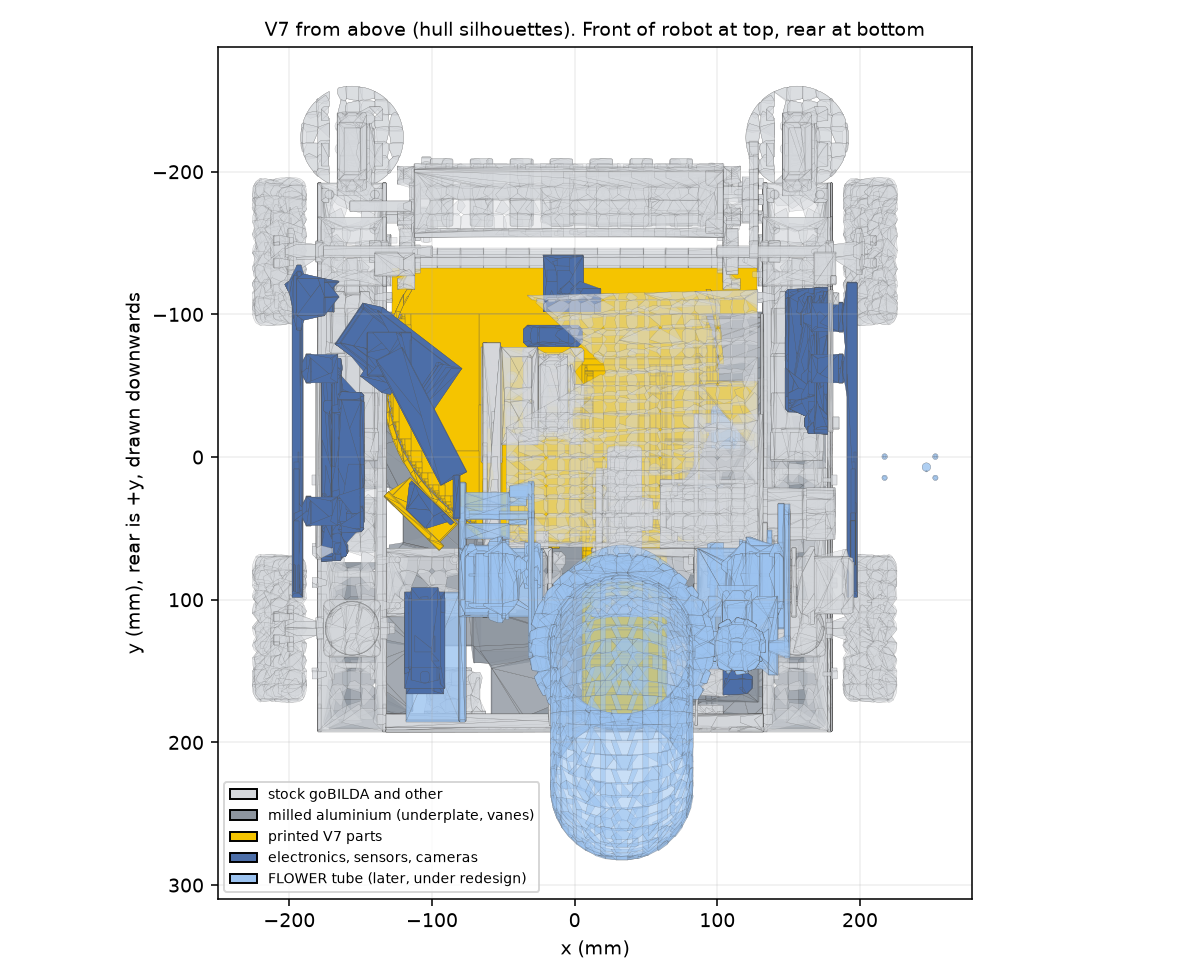
Before you start
1. Tools and consumables
- From the stock kit: 7 mm nut driver (4206-0070-0001), 3 mm and 2.5 mm hex keys, scissors for the gridplates.
- Soldering iron for M3 and M4 heat-set inserts (brass insert kit, see buy list).
- Hand drill and a 3.4 mm bit, only for one case: if the underplate was already milled before the new DXF, the 5 new rail holes are drilled by hand (B1). Everything else is milled or printed with its holes.
- Feeler gauge, steel rule, a fingernail (for the joint checks in Part C).
- Zip ties (kit, 28), M3 and M4 screws and nuts (see the part lists in each step).
- Loctite or equivalent for set screws on the REX collars and Sonic hubs (the stock guide uses set screws).
2c. Print list, update 2026-11-17
The plate table with status (printed, printing, to print) is in B0. Print defaults now: 4 walls and 20 % gyroid; 5 to 6 walls only for load parts. Yellow ABS is final, grey is a stand-in. No 3 hour or longer print starts until Mark has seen a render and the support preview. The underplate is milled from 1/8 in 6061 again (B1).
2b. Print and mill list, update 2026-11-16 (supersedes the table of 2026-11-15 below)
The full list with files, printers, plates and status is in B0. In short: plate 36 (K1C): colour clamp bar, hall bracket, laser plate, battery cradle (printing); plate 34 (K1C): rail arcs v3c and v3 (printed); plate 33c (P2S): ramp v3f (printing, reprint); plate 35 (P2S): one-piece rotor (queued); plate 37 (P2S, PLA): floor A upper (queued); plate 37e (Ender, PLA): floor A front bar (printing); plate 30 (P2S): grey hanger plate (queued). No plate yet: hub mounts L and R, sign holders L and R, one-servo frame 16j, the two carriage servo spacers. Mill: the polycarbonate underplate on the Snapmaker (B1). Plate 39 (K1C, grey ABS, 5 walls, 20 % infill; queued after rotor 35k, not printed): both corner gear carriers 16m, bevel pinion and bevel gear (print a test pair first), FLOWER wedge arms, wedge hanger, wedge servo bracket (B15, B16).
Superseded 2026-11-16, do not use: the 6061 underplate and all its DXFs; floor A as one piece (plates 22, 23, 25, the 259 mm and 251 mm files); the one-servo frame of 2026-11-15 and 16i; ramp v3 (plates 33, 33b) and the 6 mm ramp (plates 20, 28); plates 26 and 27 (hubs, rail arcs); the bolted-vane rotor and the aluminium vanes (hidden fallback); the 15d clamp bar and laser plate; the M16 laser bracket on hood H; the battery tray; sign holders 16a and v2; the Expansion Hub plate v4 and the aluminium sign brackets.
2. What to print and mill first (plates 24 to 28, 2026-11-15; partly superseded, see 2b)
Print rules for every printed part: yellow ABS, 6 walls and 30-40 % gyroid infill, never blind 100 %. No raft (brim is fine). Supports only where they snap off outside faces, never in bores, the lane or the ball path. Files are in make_2026-11-14/V7/ (names end _2026-11-15). Do NOT use the files in the superseded_* folders, and do not use the old STLs without a date.
| Order | Part | Plate and printer, or mill | Size mm | Qty | Max g | Status (2026-11-15) |
|---|---|---|---|---|---|---|
| 1 | One-servo frame | plate 24, P2S | 57 x 75.5 x 80 | 1 | 67 | printing |
| 2 | Blade gear, 23 teeth (fit-check print) | plate 24, P2S | 23.4 x 13.8 x 23.4 | 1 | 5 | printing |
| 3 | Gate gear, 14 teeth (fit-check print) | plate 24, P2S | 17.7 x 18 x 18.7 | 1 | 2 | printing |
| 4 | Wedge blade with REX hub | plate 24, P2S | 40 x 50 x 83 | 1 | 43 | printing |
| 5 | Gate arm with REX hub | plate 24, P2S | 65 x 5.8 x 18 | 1 | 4 | printing |
| 6 | Printed floor A with bearing boss | plate 25, Ender-3 S1 Plus (PLA test part) | 259 x 197.4 x 47 | 1 | 207 | printing |
| 7 | Windmill top hub and bottom hub | plate 26, K1C | OD 36 x 12 and OD 36 x 9 | 1 + 1 | 10 + 7 | printing |
| 8 | Windmill rail arc 1 (joined) and rail arc 2 (solid) | plate 27, K1C | 124.1 x 186.2 x 94 and 17.4 x 52.3 x 41 | 1 + 1 | 74 + 11 | ready |
| 9 | Printed ramp, 6 mm sheet, side blocks | plate 28, P2S | 99.6 x 140.3 x 158.9 | 1 | 101 | ready |
| 10 | Colour sensor shelf and back plate | plate 21, K1C | 50.9 x 50.5 x 21.5 | 1 | 8 | printed, good |
| 11 | Battery tray | plate 21, K1C | 128.5 x 49 x 2 | 1 | 12 | printed, good |
| 12 | Underplate, 6061 1/8 in (3.2 mm), 291 holes | mill; file V7_underplate_6061_3.2mm_top_rail_holes_2026-11-15.dxf |
352 x 291 x 3.2 | 1 | - | to mill (if already milled: drill 5 holes, B1) |
| 13 | Windmill vanes, 6061 1/16 in (1.6 mm), with notch and 2 holes each | mill; STEP and STL V7_windmill_vane_N_milled_notch_holes_2026-11-15 |
about 95 x 91.5 | 4 | - | to mill |
Print notes. Plate 24 (P2S, PolyMaker ABS-MF yellow in AMS slot 2): estimated 4 h 34 min and 106 g for all five parts. The two gears are fit-check prints (see B9); if the gate jams, reprint them in nylon or PA-CF. Plate 25 (Ender-3 S1 Plus, PLA): estimated 16 h 36 min and 209 g, 4 walls and 25 % gyroid; it is a test part. A final ABS floor needs a new slice: the older H2S ABS plate file 22 is the OLD floor A without the boss. Plate 26 (K1C): estimated 54 min and 15 g. Plates 27 and 28: the K1C gcode and the P2S 3MF are made but not started and no time is recorded; the 3MF is not sliced, so open it in Bambu Studio, check the preview (the ramp has supports on, none may touch the ball surface) and slice. Plate 21 (K1C, 1 h 28 min, 34 g) is printed: its shelf and tray are good, but the hub and the arc 2 kerb that were printed in it are superseded (the new top and bottom hubs and the solid arc 2 replace them).
Upper bound if every new printed part were solid (CAD volume x 1.04 g/cm3): 531 g plus 20 g for the shelf and tray. One 1 kg yellow spool covers it.
Superseded, do not use: two-servo blade bracket, gate servo stand, old wedge blade and gate arm (old hub bores), old hub (OD 36 x 12 with M4 pattern only), old arc 2 kerb (slit and window), old arc 1 (never printed), old 4 mm ramp (plate 20), old floor A without the boss (plates 22 and 23), the four old vanes, and the underplate DXF of 2026-11-14.
Milling: 1/8 in 1-flute, S12000 F360 (the settings that worked on the Snapmaker). The underplate (352 x 291) is tight on the Genmitsu 4030 (toe clamps must sit outside the cut) and the Snapmaker A350 size limit is not confirmed. Check whether the CAM leaves tabs, and cut and deburr them. Cut the vanes from the 1/16 in sheet (each is a flat plate; the STL is in assembly pose, so flatten it in CAM). The notch and the two 3.2 mm cross-bolt holes are in the STEP and the STL: mill them, do not drill by hand.
Parts carried over from last week (already made, or still to make). These are in the V7 model unchanged. Status from the make sheet:
| Part | Status |
|---|---|
| Intake bracket plates, 3 mm 6061, x2 (the "-16" pair) | made |
| Windmill hanger plate 3 mm and 2.4 mm spacer | plate: not confirmed made. Spacer: ABS made |
| Windmill sensor bracket, magnet clips x4, laser sensor bracket M16, C920 case halves x2 | made (K1C) |
| Pod stop blocks L and R (ABS stand-ins made), TPU pads x4 | blocks: made as stand-ins. Pads: not confirmed |
| Sign brackets x4 (ABS stand-ins), sign holders L and R | brackets: made. Holders: not confirmed finished |
| Signs 20789 (red/blue/white) | NOT made (first print failed). Redo when the spools arrive |
| Expansion Hub mount plate v4 | made |
| Control Hub mount (mirror of the EH plate) | NOT FOUND: no STL in the make folder (see Check against CAD) |
| V4 carriage plates: ground plate, carriage plate, link A, link B (3 mm 6061) | no record that any was made: mill them first (files in cad/cut_files/) |
| C270 parts (arm/case/hood/back plate), C920 camera bracket block | not confirmed made |
3c. What to buy, update 2026-11-17
The buy list is now the file closeout_2026-11-14/BIOBUZZ_V7_purchase_BoM_FINAL_2026-11-17.md. Totals there: goBILDA list $1,536.66 ($1,152.49 after the 25 % FTC discount), REV $680.50, Amazon and other $259.48, grand total $2,092.47 (goBILDA at the discount), before shipping and tax. New or changed lines since the 2026-11-16 list:
- Underplate: 1/8 in 6061 sheet (Amazon B0CFKV94ND, 2 pieces 12 x 16 in, $36.99). The polycarbonate sheet and the Snapmaker bit are not needed.
- Servos: 2 x Axon MAX MK2 2004-0025-0002 ($99.99 each) for the blade-and-gate drive and the wedge. For D3: 1 x Axon MINI MK2 2004-0025-0001 for the nest ($99.99). The 2 lift MAX servos and the roll MINI are owned.
- Power: 1 x goBILDA 6V Servo Power Injector 3125-0001-0001 ($69.99). The REV Servo Power Module is not used.
- D3: 2106-4008-1920 REX shaft (1); 2910-0920-4008 clamping collars (2); 1908-0025-0032 servo hubs (3; two may be in the bin from V5); 4001-0025-4008 coupler (a second one, for the roll pinion); 2106-4008-0560 REX stub (the roll stub); 1611-0514-4008 bearings (18 in all in the BoM).
- Wedge: 2 x 1120-0003-0096 U-channel booms; 2106-4008-2400 REX shaft; 4 x 2802-0004-0008 button-head screws; 4 M4 heat-set inserts 5.6 x 5.0.
- Servo extension cables: 150 mm x3, 300 mm x7, 450 mm x3, 600 mm x2, 900 mm x2 (spares included). See B13.
- Camera: Limelight 3A (3122-0002-0001, $189). goBILDA showed it sold out on 2026-11-17. The robot starts with the C920.
- Not confirmed: the BoM still lists the blade shaft as 2106-4008-0560, but the CAD now uses 2106-4008-0520 (52 mm). Fix the BoM line before ordering. The BoM notes still say "the underplate is polycarbonate": that note is out of date.
3b. What to buy, update 2026-11-16 (new lines)
- Polycarbonate sheet, 1/4 in (6.35 mm), at least 12 x 18 in (300 x 358 mm minimum), 1 piece, plus a scrap offcut of the same sheet for the first cut. Double-sided cloth tape for the whole sheet. 1/8 in single-flute DLC end mill (at least 8 mm of flute), and a spare 1/8 in bit as the fence gauge. Price PENDING.
- M3 heat-set inserts, 3.0 mm long, 4 + spares (floor A bar; the 3.8 mm short insert is too long). Price PENDING.
- M3 heat-set inserts, 4.2 x 5.7 mm: new this edition 26 (hub mounts 8, sign holders 8, clamp bar 2, laser plate 5, frame feet 3); with the earlier 17 that is up to about 43 M3 in all (some may overlap), so one kit is probably not enough (kit size not recorded). M4 inserts, 5.6 x 6 mm: 4 for the hub mount feet (plus the 4 in the ramp).
- goBILDA screws new or re-lengthed, by part number (count in the V7 model; "new" is what this edition added or re-lengthed): 2800-0003-0006 x 4 (floor bar); 2800-0003-0008 x 7 (2 laser plate, 5 others); 2800-0003-0010 x 9 (floor A 6, frame feet 3); 2800-0003-0012 x 7 (rails 5, ramp foot 2); 2800-0003-0014 x 11 (sign frames 8, laser module 3); 2800-0003-0016 x 14 visible, +8 hidden (hubs 8, clamp bar 2; the 8 hidden belong to the aluminium rotor fallback); 2800-0004-0008 x 57 (new: 4 hub mount feet); 2800-0004-0010 x 79 (new: 8 for pod 2 and Pinpoint); 2800-0004-0012 x 47 (new: 12 plate, 4 servo ears, 31 pegs re-modelled); 2800-0004-0014 x 8; 2800-0004-0020 x 24 (new: 4 for the carriage servo ears). Plain M4 nuts x 8 (servo ears) and M3 nuts as before.
- UNCONFIRMED goBILDA SKUs: 2800-0003-0010, 2800-0003-0012, 2800-0003-0014, 2800-0003-0016, 2800-0004-0008, 2800-0004-0020 are not confirmed to exist at goBILDA (the CAD names them by the 2800-00xx-00LL pattern). Check each product page before ordering; if one does not exist, pick the nearest length and re-check the inserts and the plate stack (the lengths were chosen to the millimetre). 2800-0004-0009 (12 x M4x9) is no longer used.
-
Hand drill bits 3.4 mm and 4.1 mm (or 4.2 mm).
-
Late 2026-11-16 (16k/16m), all hardware SKUs marked verify are not confirmed to exist: goBILDA Torque servo 2000-0025-0002 x1 (FLOWER wedge; check stock); goBILDA 24T and 72T spur gears x2 each (verify SKU and bore); REX shaft 128 mm 2106-4008-1280 (SKU unverified) x1; M4 heat-set inserts 5.6 OD x 5 long x6 + spares for the carriers (verify source); 2800-0004-0016 (M4x16, verify) x7; M4 nuts about 5 behind the pod flange (open check: only 0.4-0.6 mm room). The 2 corner Speed servos (2000-0025-0003 x2) are no longer used. The 6 x 2800-0004-0010 foot screws of 16k are not used. Details:
BIOBUZZ_BoM.md(late pass) and the screw list CSV.
3. What to buy (V7 columns of BIOBUZZ_BoM_V6_V7_2026-11-14.xlsx, updated 2026-11-15)
New for V7:
- ONE goBILDA Torque servo 2000-0025-0002 for the blade and the gate ($36.99 from the 2026-11-08 BoM, not re-checked). The second Torque servo of the earlier plan is not needed. The two Axon MINI servos are off the V7 list (the Axon servos are reserved for the FLOWER tube).
- One-servo drive: goBILDA 4001-0025-4008 clamping coupler (25T spline to 8 mm REX); 8 mm REX shafts 2106-4008-0560 (56 mm) and 2106-4008-0960 (96 mm), confirm the SKUs (inferred from the 2106-4008-LLLL pattern); 1611-0514-4008 flanged bearings (8 mm REX bore), four for the frame; M4 screws for the servo ears (4) and M3 screws for the frame foot (3).
- Windmill: one more 1611-0514-4008 bearing (order three 2-packs in all: 4 frame + 1 windmill + 1 spare), an 8 mm REX shaft 16 mm 2106-4008-0160 (confirm the SKU, or cut it from a longer shaft), and 8 x M3x16 screws with 8 x M3 nuts (owned stock).
- Rails: 5 more M3 heat-set inserts (17 inserts in all from the one kit) and 5 x M3x8 screws (owned stock).
- Carried over: 1 x Speed servo 2000-0025-0003 (carriage servo, $36.99; NOT confirmed that the kit has no spare Torque for it), battery strap 2909-0102-0250 (4-pack $3.99), brass heat-set insert kit (Amazon B0FH4JQ3VB, $9.79), yellow ABS spool ($19.99), 6061 sheet 1/8 in and 1/16 in (vendor and price PENDING).
Carried over from the 2026-11-09 list (check stock first; purchase status unknown): 1205-0001-0005 dual block mounts, 2 x 1201-0043-0002 quad blocks (V5 underplate needs 6 more than the kit), M4 screws 6/8/9/10/12/14/16/18/20 mm (goBILDA 2800/2802 series), 2811-0004-0007 M4 nuts, 1611-0514 flanged bearings (the round-bore 1611-0514-0008 also fits the 8 mm REX shafts: use it if already bought), 1908-0025-0032 servo hubs, laser distance sensor 3124-0001-0001, TJC8 extension cables (150/300/450/900 mm), JST PH cables 3804-0707-0600, REV colour sensor V3 (second unit), REV-31-1387 switch, REV-31-1462 magnetic limit switch, 6 x 3 mm magnets, 3 x 6 mm dowel pins, VHB tape, Logitech C270, nylon washers and plate, grommets, red/blue/white ABS for the signs.
PENDING in the BoM: the price of the coupler, the three REX shafts and the 4008 bearings (not read); an extension cable for the one new servo; the two aluminium sheets. The servo horn line and the M2.5 ear-screw line are gone for V7.
Total to buy for V7 in the BoM: $543.55 (of which $54.74 are "check stock" items, so $488.81 without them), not counting PENDING lines (8 lines). The V6 columns and the "Two robots at once" columns of the BoM were not updated.
Part A: The stock build
Build the stock robot with the goBILDA guide open beside this book. Stock page and step numbers are written for each chapter. Kit parts that V7 does not use are listed at the end of A6.
Parts that V7 does not use from the kit: Battery Mount 1209-0001-0001 and its strap 2902-0102-0250 (replaced by the printed tray), Medium Gridplates E, F, G, Small Gridplates A (x4) and B, the three 43 mm 6 mm round standoffs 1501-0006-0430 (step 45).
A1. Frame and intake bar (stock steps 1-9, pages 8-11)
| Step | Page | Status |
|---|---|---|
| 1 | 8 | as stock. Rail 1: 15-hole channel, hub-shafts, miter gears. |
| 2 | 8 | as stock. Two dual block mounts and the 43 mm REX standoff. |
| 3 | 8 | skip: the battery mount and strap are not used. The battery goes on the printed tray (B10). |
| 4 | 9 | as stock. |
| 5 | 9 | as stock. The 24 mm REX standoff is in the model. |
| 6 | 9 | as stock. Slide the 16 rollers on the 264 mm shaft. Set the bar aside. |
| 7 | 10 | change: do NOT fit the bar to rail 2 here. The V7 bar sits 16 mm lower and 10 mm further forward, on two aluminium bracket plates. Fit it in B2. |
| 8 | 10 | as stock. Two 10-hole low channels. (See Check against CAD C1: the middle one is named "split" in the export.) |
| 9 | 11 | change: join the two halves with the four 12 mm screws as stock. The single 10 mm screw that seats the bar end is not used. |
Hub-shafts turn freely with no end play (steps 1 and 4). Frame is square.
Proposed (dry fit first): slide the six 1201-0043-0002 quad blocks into the rail cavities now, while each rail channel is still open (three per rail, see B1). The V5 book did this late and had to take other parts off. If a block does not go in, leave it for B1.
A2. Drive gearboxes (steps 10-14, pages 11-13)
Steps 10, 11, 12, 13, 14: as stock. Four 19.2:1 motors, two surface mounts 1222-0001-0001, eight miter gears in phase (Figures 11-A and 14-A).
Gears in phase, motors turn by hand.
A3. Intake pod (steps 15-31, pages 14-19)
Steps 15-18 (p14), 19-22 (p15; the second "STEP 25" on page 15 is really step 20), 23-25 (p16), 26-28 (p17), 29-30 (p18), 31 (p19): as stock, with one change:
- Step 19 (p15): change: the flanges of the 8-hole U-channel (1120-0008-0216, the Gecko beam) are trimmed in V7 (the intake rig study found 15 mm trimmed is enough, 10 mm the minimum). The exact cut is Check against CAD C3. Do not cut until it is checked.
Pod floats and returns. 100-tooth and 20-tooth gears aligned; about 4 mm gap (Figure 31-A).
A4. Corner Geckos and mecanum wheels (steps 32-34, pages 20-21)
Steps 32, 33 (p20) and 34 (p21): change (2026-11-16). Build the two 72 mm Gecko corner wheels, the four mecanum wheels (deep side out, Figure 34-C) as stock, but do not build the two Speed-servo modules: the corner wheels are driven by gears from the pod axle (B15). The servo modules, their 4 x 2800-0004-0020 standoff screws and 3 x 1516 bar screws are gone.
A5. Uprights and shooter motor (steps 35-40, pages 22-25)
| Step | Page | Status |
|---|---|---|
| 35 | 22 | as stock. Left upright with two quad blocks. In V7 the left upright is x -64..-16 (not at the stock outer position): see Check against CAD C5. |
| 36 | 22 | as stock. Right upright, quad block and 2-hole channel. |
| 37 | 23 | change: the 5-hole low channel does not go on as shown. In V7 one 5-hole low channel (1121-0005-0144) is sawn to y > -30 and becomes the carriage bar (B5). The other one is the windmill beam (A7). Which is which: Check against CAD C6. |
| 38 | 23-24 | as stock for the conversion to 1:1 with coupler 5105-0208-0019 (Figure 38-B). The motor then rides on the carriage, not fixed (B5). |
| 39 | 25 | skip: the carriage replaces this fixed joint (B5). |
| 40 | 25 | change: bolt the left upright assembly to the base with its stock screws. The right upright is bolted on in B5 with the carriage ground plate. |
A6. Gridplates, ramp and walls (steps 41-50, pages 26-31)
| Step | Page | Status |
|---|---|---|
| 41 | 26 | change: cut ONLY plates C (x2), D and H (cut-line sheets pages 5 and 7). Do not cut A, B, E, F or G. Fit the two C plates inside the uprights with 2 zip ties each. In V7 they sit one hole pitch (8 mm) lower with the tower (B5). |
| 42 | 26 | as stock. Plate D on the 15-hole channel, 2 zip ties. |
| 43, 44 | 27 | skip: plates E, F, G are replaced by the printed floor and ramp. |
| 45 | 28 | skip: the three 43 mm standoffs are not used. |
| 46, 47 | 28-29 | skip. |
| 48, 49 | 30 | skip. |
| 50 | 31 | skip: plate B is not used. |
A7. Hogback wheel and windmill (steps 51-56, pages 31-33)
| Step | Page | Status |
|---|---|---|
| 51 | 31 | as stock. Hogback 3626-0014-0096 on Hyper Hub 1310-0016-4008. |
| 52 | 32 | as stock. Windmill (Torque) servo 2000-0025-0002 in a Compact ServoBlock with a quad block. |
| 53 | 32 | skip: the four small A plates are replaced by the milled aluminium vanes (B7). |
| 54 | 32 | change: the 5-hole low channel is the windmill beam (1121-0005-0144, x -64..-52, y -80..64, z 96..144). The windmill hangs from it on the hanger plate (3 mm 6061) and the 2.4 mm spacer. |
| 55 | 33 | change: put the wheel on the motor shaft with the 1 mm gap as shown, then add the two flywheel discs (B5). |
| 56 | 33 | change: hang the windmill on the beam with the hanger plate as described in B7. |
A8. Hood (step 57, page 34)
Step 57: change: fit Large Gridplate H with the six zip ties, but one hole pitch (8 mm) lower with the tower, and keep the zip ties off the carriage bar. Whether H is cut for the camera view in V7 is Check against CAD C7. The laser sensor bracket bolts to H (B11).
End of Part A: the base of the stock robot (without battery mount, deck or ramp) drives and strafes on the bench.
Part B: V7 changes, in build order
Order note: the ramp bolts to the side plates C and rests on the base channel, and the windmill hangs from the left upright. So the tower and carriage (B5) come before the ramp (B6) and the windmill (B7). Everything else follows the order the team asked for.
B0. What changed on 2026-11-15 (late) and 2026-11-16, and the order to build it
Print rules: no raft (brim is fine); supports only where they snap off outside faces, never in bores, the lane or the ball path. Default 4 walls and 20 % gyroid (updated 2026-11-17; 5 to 6 walls only for load parts). Team default is yellow ABS: yellow = final, grey = stand-in. Two floor A parts are PLA on purpose (test parts, Mark). Every printed part gets its pre-print check card and Mark's OK before the print starts. Files are in make_2026-11-14/V7/; the check cards are in print_profiles/out/preprint/.
Print plates and status, 2026-11-17 (from the print log, read late on 2026-11-17)
Printed means the log says done, or Mark said it is finished. Printing means started with no finish note. To print means not started. Colour: yellow = final part, grey = stand-in (to be replaced). The log changes during the day: check print_profiles/print_log.csv before you plan a print.
| Plate | Printer | Parts | Colour | Status | Notes |
|---|---|---|---|---|---|
| 33c | P2S | Ramp v3f (gussets) | yellow | printed | Mark: "looks great". Not reprinted (floor A was re-made to fit it) |
| 37y | P2S | Floor A upper (F17b) + 2 ramp keepers | blue PETG | printed | Replaces plates 37 and 37u. Fits the ramp (B3). 4 walls 20 %, no supports, no brim, bed 70 C, est 4 h 09 min, 147 g |
| 37e | Ender | Floor A front bar | purple PLA | printed | Unchanged. Needs clean-up |
| 37u | Ender | Old floor A upper (slot roofs) | purple PLA | printed, superseded by 37y | Do not use |
| 34 | K1C | Rail arc 1 v3c, rail arc 2 v3 | yellow | printed | Fit not checked in the sources |
| 36 | K1C | Colour clamp bar, hall bracket, laser plate, battery cradle | yellow | printed | |
| 35k | K1C | One-piece rotor v3 | grey | printed | A stand-in: Mark will replace it with a part with aluminium fins (B7) |
| 38p | P2S | One-servo frame 16j + 2 carriage-servo spacers | yellow | printed | Frame needs a hand counterbore for the bearing flanges (B8). Reprint file: ..._frame_print_2026-11-17s3.stl (no plate yet) |
| 39 | K1C | Corner gear carriers L and R (16m) | grey | printed | Its bevel pair has a D bore and is not used (see 39r) |
| 39r | K1C | Corner bevels: 2 pinions 9T, 2 gears 17T, REX hex bore | yellow | printed | Final bevels (B15). 37 min, 8 g |
| 40 | P2S | goBILDA 24T and 72T test gears (printed copies) | yellow | printed | Test copies. The real gears are goBILDA steel and acetal |
| 41h | K1C | Wedge v4 posts L and R, right arm, hanger plate (old design) | grey | printed | The grey fit-test set. Not final |
| 44 | K1C | Wedge posts L and R, crossing arms L and R (v4 hole positions) | yellow | printed | Holes do not match the real channel: rescue the channels, or print 44b (B16) |
| 52 | K1C | D3 Q1 slide (D3c, upside down, no supports) | yellow | printed | 7 h 03 min est, 180 g |
| 51 | K1C | D3 P2 sleeve (flange down, no supports) | yellow | printing | Started after Mark reviewed the render |
| 54 | P2S | D3 Q2 hairpin half B | yellow | printing | Tree supports under the outside. Mark added a PETG support interface |
| 42s | P2S | Wedge v5 arms (left and right) | yellow | printing or done (no finish note in the log) | Mark started the arms alone first |
| 42t | P2S | Wedge v5 ramp body | yellow | printing | No supports. Bambu Studio showed 3 h 02 min |
| 50 | P2S | D3 P1 funnel + roll pinion (new pinion pocket) | yellow | to print | The hold was lifted after the S2 fix. 5 h 26 min est, 150 g |
| 51b | K1C | D3 roll servo bracket | yellow | to print | Needs supports. 1 h 34 min est, 38 g |
| 53 | P2S | D3 Q2 hairpin half A | yellow | to print | Redesign under review (53a). Keep 53 for now. 5 h 27 min est, 122 g |
| 55 | K1C | D3 swing arms, cranks, links, axle clamps, pin-P spacer | yellow | to print | 6 walls (load parts). 1 h 47 min est, 35 g |
| 56 | K1C | D3 nest flap + nest servo carrier | yellow | to print | 2 h 01 min est, 52 g |
| 44b | K1C | Wedge v6 posts and crossing arms (new holes) | yellow | to print (or rescue plate 44) | 2 h 56 min est, 75 g |
| 11c | K1C | C920 case (base, lid) + adapter, landscape | yellow | to print | 1 h 57 min est, 49.5 g |
| 10c | K1C | C270 case: shell, back plate, adapter | yellow | to print | 2 h 03 min est, 46.5 g |
| 10d | K1C | C270 arm | yellow | to print | 1 h 03 min est, 25 g |
| none | P2S | Hub mounts L and R, sign holders L and R | yellow | on hold (Mark) | No plate made |
Times are Orca estimates. The P2S in Bambu Studio can show about twice as long. D3 total: about 1,000 g of yellow ABS, one full 1 kg spool across both printers (check stock). The windmill hanger plate (plate 30, grey) was printed with plate 41h.
New and changed parts, latest versions only (status column is of 2026-11-16: the table above is newer)
| Part | Latest file | Printer and material | Plate | Status 2026-11-16 | Supersedes |
|---|---|---|---|---|---|
| Underplate, 1/4 in (6.35 mm) polycarbonate, 28 holes | CAD V7_underplate_PC_6.35mm_2026-11-16j.stl; mill from V7_underplate_6061_3.2mm_NEEDED_HOLES_ONLY_2026-11-16c.dxf; CNC files in cad/cnc_underplate_pc/ |
Snapmaker A350, 1/8 in 1-flute DLC, polycarbonate | CNC files, no plate | not cut yet; scrap test first | 1/8 in 6061 underplate (all older DXFs) |
| Hub mount left (Expansion Hub, honeycomb) | V7_hub_mount_left_EH_honeycomb_2026-11-16a.stl |
P2S, ABS (the work order says PETG; ABS is the team default, confirm) | none assigned | waiting on go | Expansion Hub plate v4, K2 bay |
| Hub mount right (Control Hub, honeycomb) | V7_hub_mount_right_CH_honeycomb_2026-11-16a.stl |
P2S, ABS (same note) | none assigned | waiting on go | Control Hub mount (file was missing) |
| Sign holder left (on hub mount) | V7_sign_holder_left_on_hub_mount_2026-11-16b.stl |
P2S, ABS | none assigned | waiting on go | holders 16a and v2 |
| Sign holder right (on hub mount) | V7_sign_holder_right_on_hub_mount_2026-11-16b.stl |
P2S, ABS | none assigned | waiting on go | holders 16a and v2 |
| Colour sensor clamp bar | V7_colour_sensor_clamp_bar_2026-11-16e.stl |
K1C, yellow ABS | 36 | printing (started 2026-11-16) | clamp bar 15d (no holes) |
| Laser adapter plate | V7_laser_adapter_plate_2026-11-16e.stl |
K1C, yellow ABS | 36 | printing | laser plate 15d; M16 bracket on hood H |
| Hall sensor bracket | V7_hall_sensor_bracket_2026-11-15d.stl |
K1C, yellow ABS | 36 | printing | none (first drawn) |
| Battery cradle | V7_battery_cradle_2026-11-15d.stl |
K1C, yellow ABS | 36 | printing | battery tray (plate 21) |
| Printed ramp v3f (44 deg gussets) | V7_ramp_v3_chamfered_2026-11-16f.stl |
P2S, Polymaker ABS-MF yellow (AMS slot 2), on its side | 33c | printing (reprint: the first 33c lost adhesion, plate washed, same file) | ramp v3 (plates 33 and 33b failed), 6 mm ramp (plates 20, 28) |
| Floor A upper | V7_floor_A_P2S_upper_2026-11-16h.stl |
P2S, PLA (Geeetech silk, slot 3) | 37 | queued; Mark reviews it in Bambu Studio first | floor A 259 mm and 251 mm (plates 22, 23, 25) |
| Floor A front bar | V7_floor_A_front_bar_2026-11-16h.stl |
Ender-3 S1 Plus, purple PLA | 37e | printing (started 2026-11-16, est 2 h 44 min, 35 g) | the strip of the old floor A |
| One-servo frame | V7_one-servo_frame_print_2026-11-16j.stl |
P2S, yellow ABS (Polymaker ABS-MF) | none yet (the 2026-11-15 frame was on plate 24) | waiting on go: reprint | frame 2026-11-15 and 16i |
| V4 carriage servo ear spacers A (y 66) and B (y 113) | V4_carriage_servo28_ear_spacer_A_y66_2026-11-16j.stl, ..._B_y113_... |
ABS (printer not assigned) | none assigned | waiting on go | none (new) |
| One-piece windmill rotor v3 | V7_windmill_rotor_ONE_PIECE_3mm_print_2026-11-15c.stl |
P2S, ABS, right side up, tree supports | 35 | queued | bolted-vane rotor (hubs and aluminium vanes) |
| Rail arc 1 v3c and rail arc 2 v3 | ..._rail_arc_1_one_piece_foot_lintel_2026-11-15c.stl, ..._rail_arc_2_kerb_foot_pads_2026-11-15b.stl |
K1C, yellow ABS | 34 | printed 2026-11-16 (3 h 43 min, no errors); fit not checked | rail arcs of plate 27 |
| Windmill hanger plate (grey stand-in for the milled 6061 plate) | cad/cut_files/test_print/windmill_hanger_plate_TEST_PRINT.stl |
P2S, grey ABS | 30 | queued | none |
| Corner gear carrier LEFT 16m (4 M4 inserts) | V7_corner_gear_carrier_left_2026-11-16m.stl |
K1C, grey ABS, 5 walls 20 % | 39 | queued (after rotor 35k); NOT printed | corner carrier 16k (obsolete) |
| Corner gear carrier RIGHT 16m (mirror) | V7_corner_gear_carrier_right_2026-11-16m.stl |
K1C, grey ABS | 39 | queued; NOT printed | corner carrier 16k (obsolete) |
| Bevel pinion 9T, module 1.6, 30 deg (x2, print a test pair first) | V7_corner_bevel_pinion_9T_m1.6_PA30_2026-11-16k.stl |
K1C, grey ABS | 39 | queued; NOT printed | the 2 corner Speed-servo modules |
| Bevel gear 17T, module 1.6, 30 deg (x2) | V7_corner_bevel_gear_17T_m1.6_PA30_2026-11-16k.stl |
K1C, grey ABS | 39 | queued; NOT printed | the 2 corner Speed-servo modules |
| FLOWER wedge arms (one piece, both arms) | V7_FLOWER_wedge_arms_2026-11-16m.stl |
K1C, grey ABS | 39 | queued; NOT printed | none (new) |
| FLOWER wedge hanger left | V7_wedge_hanger_left_2026-11-16m.stl |
K1C, grey ABS | 39 | queued; NOT printed | none (new) |
| FLOWER wedge servo bracket left | V7_wedge_servo_bracket_left_2026-11-16m.stl |
K1C, grey ABS | 39 | queued; NOT printed | none (new) |
Order of assembly for the new and changed parts (updated 2026-11-17)
- Underplate. Check the milled 1/8 in 6061 plate against the DXF: 28 holes (B1).
- Chassis and odometry. Blocks, then the plate with 12 x 2800-0004-0010; pod 2 and the Pinpoint with 8 x 2800-0004-0010 (B1). Check the pod 2 swing (6 mm clear).
- Floor A (PETG, plate 37y). Press 6 M3 inserts from below, the 4 short (3.0 mm) inserts for the front bar, and the 4 keeper inserts. Screw the bar to the upper part (4 x 2800-0003-0006). Fix the floor to the plate with 6 x 2800-0003-0006 (B3).
- Rails and ramp. Rails: 5 x 2800-0003-0008 from below. Ramp foot: 2 x 2800-0003-0008. Drop the ramp into the open seat, then fit the 2 keepers with 4 x 2800-0003-0012. Ramp side blocks 4 x 2800-0004-0010 (B4, B6).
- One-servo frame (counterbore the bearing seats first) with 3 inserts and 3 x 2800-0003-0008 under the plate; the Axon MAX on the servo plate with 4 x 2800-0004-0012 and nuts; then the coupler, the 52 mm blade shaft, gears, blade and gate arm (B8, B9).
- V4 carriage servo spacers and 4 x 2800-0004-0020 (B8).
- Windmill on its axle and bearing (B7).
- Sensors: colour clamp bar, hall bracket, laser plate (B11).
- Battery cradle (B10), then the servo power injector on the rear channel web (B12).
- Hub mounts, hubs, sign holders (B12), when the hold is lifted.
- Wiring with the longer hub cables and the extension cables (B13).
- Corner-wheel gear drive (B15): carriers on the pod, goBILDA 24T and 72T gears, the yellow REX bevels; restore the pod rest stops (B2).
- FLOWER wedge (B16): posts and booms first, then the arms, ramp and servo.
- Cameras (B11): tap the mount L holes first.
- FLOWER D3 tube and lift (B14), on build day after the bench checks.
Decided: front corner wheels are KEPT and gear-driven (Mark, 2026-11-16)
This replaces the earlier "pending decision". Round 40 (intake only, n = 30 per case) found the corner wheels do not matter for balls inside the roller bar width (30/30 either way) but do matter beyond about 128 mm to the side of the centre line (at 150 mm off: wheels on 30/30, off 23-25 of 30). Mark's answer: KEEP them, drive them from the pod axle with gears at the tested speed, mounted on the pod. The wheels could not move back (rail flanges), so the robot stays 456.0 mm long against the 457.2 mm limit (1.2 mm margin; the pod 2 and Pinpoint screw heads reach y 196.0). The 2 corner servos are gone. The gear drive is not simulated (Mark: bench test). See B15.
B1. Underplate (1/8 in 6061 again, 2026-11-17), quad blocks and odometry
B1 update 2026-11-17: back to 1/8 in (3.175 mm) 6061
Mark switched the underplate from 1/4 in polycarbonate back to 1/8 in 6061. The work order says it was milled on the evening of 2026-11-17 from V7_underplate_6061_3.2mm_NEEDED_HOLES_ONLY_2026-11-16c.dxf (352 x 291 mm, 28 holes: 16 x D3.4 and 12 x D4.1). The CAD file is V7_underplate_6061_3.175mm_2026-11-17u1.stl.
- Which face stays: the TOP, at z -24. The channels, floor A, the ramp foot, the rail arcs, the frame feet and the windmill bearing all sit on z -24. Nothing else moved. The bottom is now z -27.175 (it was -30.35).
- Every hole a part needs is in the DXF. All 28 screws that pass through the plate sit on DXF holes. The windmill bearing sits on the plate and has no hole, as designed.
- Weight: 825 g for the 6061 plate against 733 g for the polycarbonate one (+92 g). The shorter screws save about 3 g.
- Under the plate only the 28 screw heads hang below (M4 head bottom z -31.17, M3 head bottom z -30.18). Plate bottom clearance to the tile rises from 17.85 to 21.03 mm.
Screws through the plate (28 in all; heads at the new bottom)
| Where | Count | Screw | Was (polycarbonate) | Engaged |
|---|---|---|---|---|
| Plate to the quad blocks at x = +-140 and +-172, y 16 / 88 / 152 | 12 | 2800-0004-0010 (M4x10) | M4x12 | 4.3 mm in the block |
| Rail arcs 1 and 2 (5) and the ramp foot (2), into M3 inserts | 7 | 2800-0003-0008 (M3x8) | M3x12 | 4.8 mm |
| One-servo frame feet, into 4.2 x 5.7 inserts | 3 | 2800-0003-0008 (M3x8) | M3x10 | 4.8 mm |
| Floor A inserts, 4.2 mm bores, 6 positions | 6 | 2800-0003-0006 (M3x6) | M3x10 | 2.8 mm (M3x8 would pass the bore ceiling by 0.8 mm) |
| Floor A front bar at y -125 (do not pass through the plate) | 4 | 2800-0003-0006 | unchanged |
Pod 2 and Pinpoint screws (4 + 4 x 2800-0004-0010, from outside the rear web) are unchanged.
Steps (2026-11-17)
- Lay the plate on the DXF printout or
layout.png: 28 holes, the widened pod notch, no burrs. - Fit the six quad blocks, then lift the robot on blocks and fit the 12 x 2800-0004-0010 plate screws.
- Fit pod 2 and the Pinpoint (4 + 4 x 2800-0004-0010). Check the pod 2 swing through its notch (the pod notch only gains room with the thinner plate).
Check: The plate lies flat with no rocking. Screw heads are below the plate. Pod 2 swings freely. Robot length is still within 457.2 mm in the sizing box. Not verified: the real thread depth in the 1201 block (the model shows the screw overlapping the block thread by about 9 mm3 each; the hole runs through the block, so nothing bottoms out).
Superseded 2026-11-17: everything in "B1 update 2026-11-16" below (the 1/4 in polycarbonate plate, its Snapmaker factory-edge method, its screw lengths M4x12, M3x12, M3x10). The hole list, the pod 2 clearance and the robot length (456.0 mm) in it still hold.
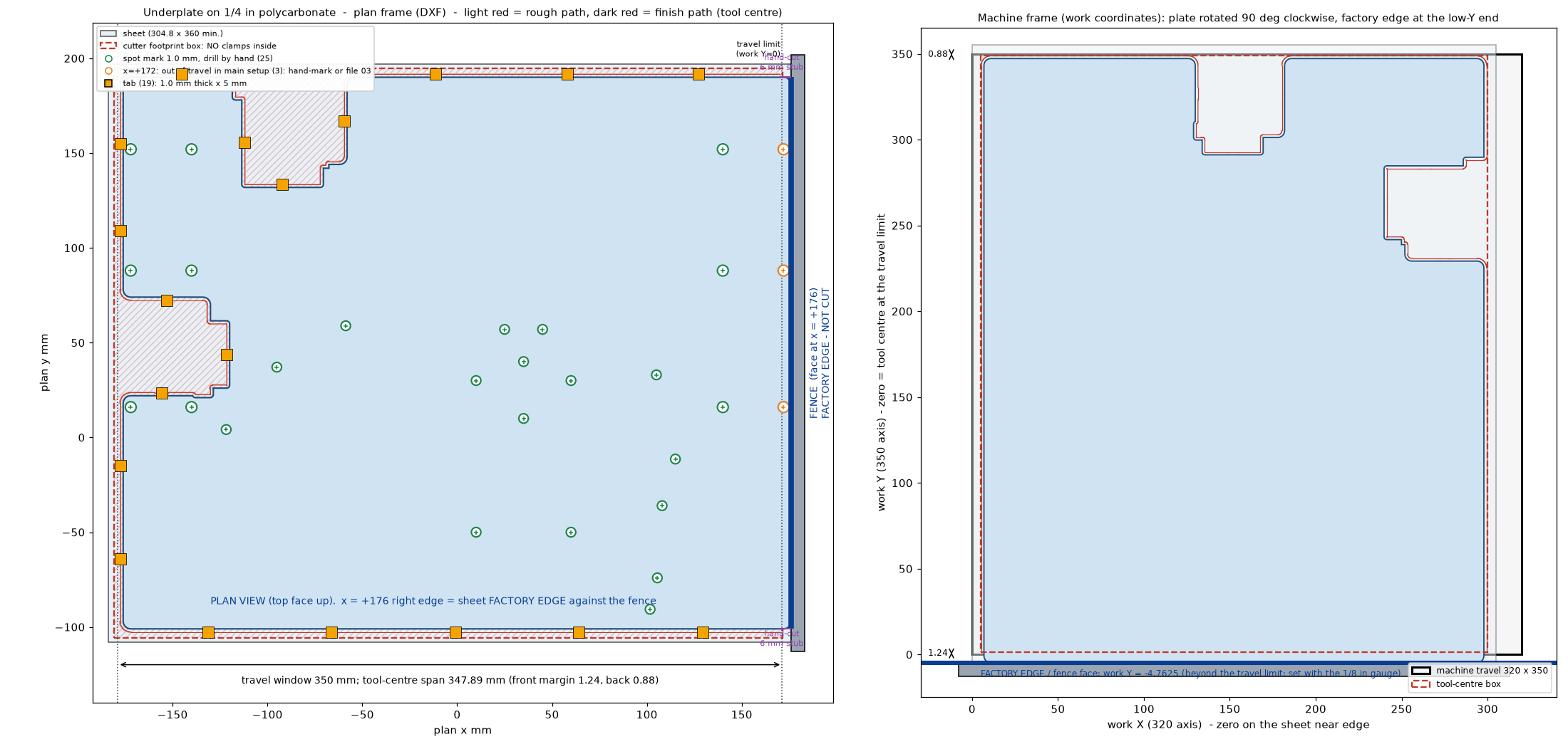
B1 update 2026-11-16: 1/4 in polycarbonate underplate (replaces the 6061 plate)
The CAD underplate is now 1/4 in (6.35 mm) polycarbonate, top z -24, bottom z -30.35, every hole and notch kept, the pod notch widened as in the 16c outline. The CAD file is V7_underplate_PC_6.35mm_2026-11-16j.stl. The aluminium 1/8 in plate (and every older DXF, including the 291-hole plate described below) is superseded. Status note: the decisions list of 2026-11-16 says Mark was still waiting to see whether the school's CNC is set up; the CAD, the screw list and the CNC job already follow the polycarbonate plan, so this chapter does too. If the aluminium plate is wanted back, the same DXF works, but the screw lengths below change back.
Parts
| Part | Qty | File or part number |
|---|---|---|
| Polycarbonate sheet 1/4 in (6.35 mm), at least 12 x 18 in (minimum 300 x 358 mm, cut square) | 1 | measure the real thickness; edit THICK in gen.py if it is not 6.35 |
| Mill outline and holes | V7_underplate_6061_3.2mm_NEEDED_HOLES_ONLY_2026-11-16c.dxf (352 x 291 mm, 28 holes: 16 x D3.4 for M3, 12 x D4.1 for M4); job files underplate_00_air_test.cnc, _01_spots.cnc, _02_outline.cnc, _03_OPTIONAL_right_edge_spots.cnc in cad/cnc_underplate_pc/ |
|
| Bit | 1 | 1/8 in single-flute DLC end mill, at least 8 mm of flute, stick-out about 14 mm; a spare 1/8 in bit (3.175 mm) is the fence gauge |
| Hand drill bits | 3.4 mm and 4.1 mm (or 4.2 mm) | |
| Plate screws, 2800-0004-0012 (M4x12) | 12 | was M4x9 (2800-0004-0009); heads at the new bottom (z -30.35), tips z -18.35, up through the plate into the quad blocks at x = +-140 and +-172, y 16 / 88 / 152 (the 2026-11-15 text below says y 12 / 84 / 148; the DXF holes are at 16 / 88 / 152: use the DXF) |
| Pod 2 screws 2800-0004-0010 (M4x10) | 4 | pod 2 inside the REAR channel 1121-0010-0264:2, x -100 and -68, z -16 and +16, from outside; heads on the web outer face y 192.0..196.0 |
| Pinpoint screws 2800-0004-0010 (M4x10) | 4 | Pinpoint mount block 3117-0032-0016 against the same web, x 68 and 100, z -16 and +16 (confirm the block holes are tapped) |
Screw lengths with the thicker plate (28 screws changed; the heads now sit at the new bottom):
| Where | Was | Now | Count |
|---|---|---|---|
| Plate to quad blocks | M4x9 (2800-0004-0009) | 2800-0004-0012 | 12 |
| Rail arcs 1 and 2 (5) and ramp foot (2), into M3 inserts | M3x8 | 2800-0003-0012 | 7 |
| Floor A upper to the plate, 6 positions | M3x6 | 2800-0003-0010 | 6 |
| One-servo frame foot, 3 positions | M3x8 | 2800-0003-0010 | 3 |
| Floor A front bar, 4 positions at y -125 | M3x6 | stays 2800-0003-0006 | 4 (these do NOT pass through the plate: see B3) |
Milling it on the Snapmaker: the factory-edge method (read cad/cnc_underplate_pc/SETUP.md first). These are first-try settings; nothing has been cut yet.
- Why a special method: the tool-centre travel on the 350 mm axis is 347.89 mm, so the cutter can never reach the sheet's factory edge (4.76 mm beyond the travel limit). The factory edge becomes the plate's right edge and is not cut: it is the fence reference. Check it first with a steel straight edge (no light gap over 0.2 mm across 291 mm) and a square against the adjacent factory edge. If it is chipped or bowed by more than 0.2 mm, do not cut.
- Fence: a straight bar along the X travel, trammed to within 0.05 mm over about 290 mm. Position it with the spare 3.175 mm bit as a gauge (fence face 4.7625 mm behind the tool centre) and set work Y0 with the tool at the travel limit, not at the edge. Butt the sheet's factory edge to the fence, centre the sheet in X (near edge about 7.6 mm from the X limit), touch off X0 and Z0 (top of the sheet, paper).
- Sheet: peel the film from the top face only; double-sided cloth tape under the whole sheet. Trim the 18 in length to about 14.25 in. The cutter footprint box (x -179.2..171.6, y -104.2..193.2 in plate coordinates) nearly fills a 12 in sheet, so there is almost no room for toe clamps: hold it with tape, the fence, clamps on the spare sheet end beyond the left cut, and the 19 tabs and 2 stubs.
- Order: scrap offcut test of the same sheet and bit; check the travel with
underplate_00_air_test.cnc(spindle off, about 3 min);underplate_01_spots.cnc(25 spot marks, 1.0 mm deep);underplate_02_outline.cnc(about 16 min, stay with it). Do not move or re-zero the sheet between 01 and 02. - First-try feeds: M03 S10000; rough F700 (0.07 mm/rev), finish F800, ramps F600, spot plunge F200, step-down about 0.93 mm, through depth Z -6.55 (thickness + 0.2). No coolant or solvent (it stress-cracks polycarbonate); a gentle air blast on the slot. Stop at once on melted gum on the flute, plastic strings, squealing or the sheet lifting. If it melts, raise F by 100-200 (never lower), lower S to 8000 or cut the step-down to 0.7 mm.
- After the job: snap or cut the 19 tabs and file flush; saw through the two 6 mm x 6.35 mm corner stubs along the edge line (the top and bottom edge cuts stop at x = +170); deburr. The corner stays square (no R4); file a radius if wanted.
- Hand-drilling (16 x D3.4, 12 x D4.1): drill from the top at each spot mark, slowly, with a backing board. The three holes at x = +172 (y = 16, 88, 152) are not in the spot file: hand-mark them (scribe 4.0 mm in from the factory edge) or use optional file 03 with a 3.0 mm spacer, set after the outline is done.
- Not verified (do not assume): which machine axis is the 350 mm one (
LONG_AXISingen.py), the soft limits, that jogging to the limit gives work Y = 0 as described, whether the bed extends under the fence, flute length and collet nut clearance, the feeds themselves, and the run time (about 17.8 min for spots plus outline).
Pod 2 clearance. With the plate z -30.35..-24 and the 16c outline, pod 2's minimum clearance is 6.26 mm at rest (moving), arms 8.5 mm, fixed mount block 6.36 mm (needs 6). The old outline gave 4.43 mm. Robot length: y -260.0..196.0 = 456.0 mm against 457.2 mm (18 in): 1.2 mm margin, because the 8 pod 2 and Pinpoint screw heads reach y 196.0.
Steps (2026-11-16)
- Measure the sheet, check the factory edge, mill and finish the plate as above (scrap test first).
- Drill the 28 holes and compare with the DXF and
layout.png: 28 holes, the widened pod notch, no burrs. - Fit the six quad blocks, then lift the robot on blocks and fit the 12 x 2800-0004-0012 plate screws.
- Fit pod 2 and the Pinpoint with 4 + 4 x 2800-0004-0010 from outside the rear web. Check the pod 2 swing through its notch (6 mm clear).
Check: The plate lies flat with no rocking. Screw heads do not stand proud of the plate by more than expected (heads are at the new bottom). Pod 2 swings freely. Robot length still within 457.2 mm in the sizing box.
Earlier text of this chapter (2026-11-15), kept for history
Where it disagrees with the 2026-11-16 text above, the 2026-11-16 text wins. Parts marked superseded are not used.
Superseded 2026-11-16: the 291-hole 1/8 in aluminium plate and the 12 x M4x9 screws below.
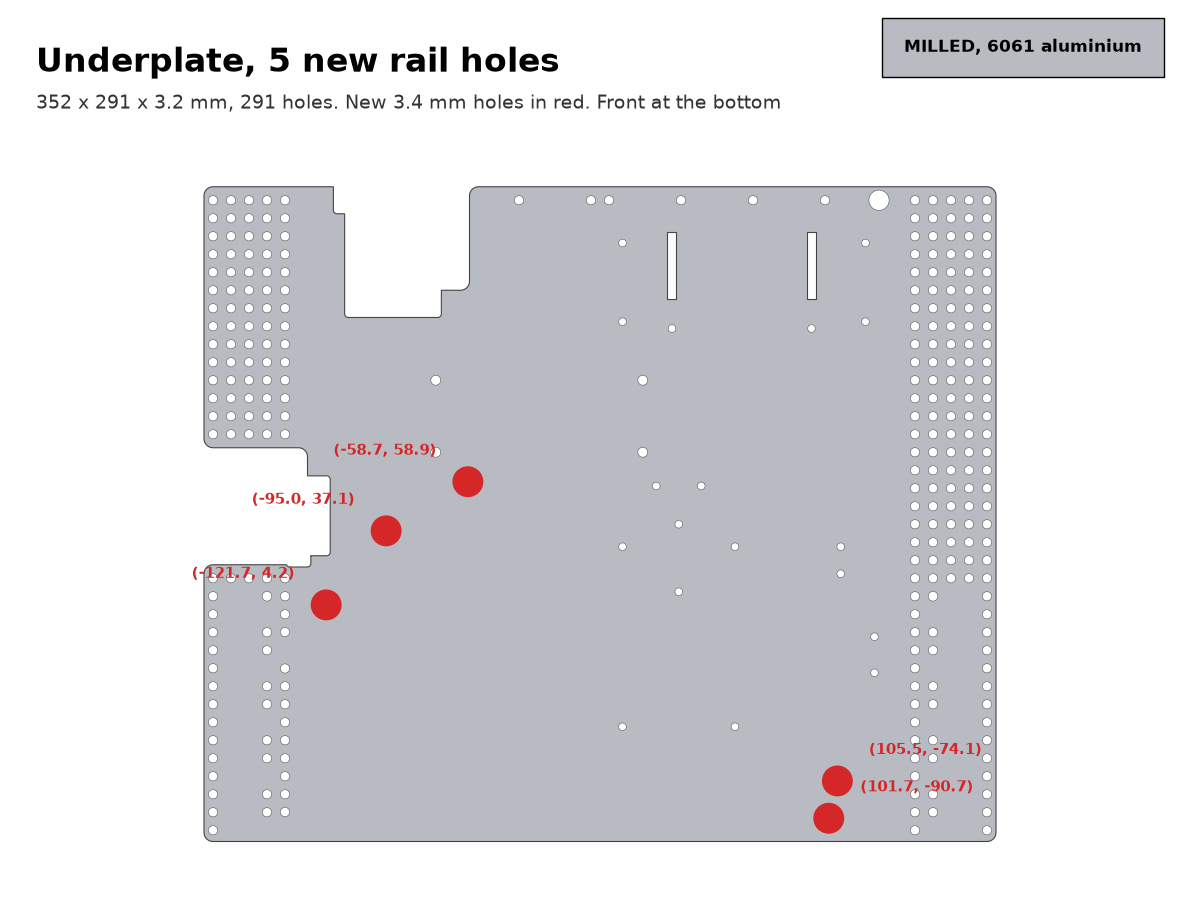
Parts
| Part | Qty | File or part number |
|---|---|---|
| Underplate, milled 6061 3.2 mm | 1 | V7_underplate_6061_3.2mm_top_rail_holes_2026-11-15.dxf (291 holes; the STEP and STL of the same date match it) |
| Quad block mount 1201-0043-0002 | 6 | three per rail cavity at y 16, 88, 152 (blocks standing on edge, 43 across, 12 thick along the rail) |
| Wall screws M4x6 socket (2800-0004-0006) | 12 | through the OUTER rail wall, two rows per block |
| Plate screws M4x9 socket (2800-0004-0009) | 12 | up through the plate into the blocks, at x = +-140 and +-172, y 12 / 84 / 148 |
| Odometry pods 3110-0001-0002 | 2 | pod 1: left cavity y 26..70. Pod 2: x -106..-62, y 148..189 |
| Pinpoint 3110-0002-0002 | 1 | x 64..104, y 171..190 |
| Pod 1 screws M4x10 socket (2800-0004-0010) | 4 | x -184..-170, y 28..36 and 60..68 |
The plate has 291 holes (261 x 4.1 goBILDA grid, 23 x 3.4 M3, 4 x 4.4, 2 x 4.3, 1 x 9.0), two strap slots 4 x 30 (x about 32 and 94, y 140..170) and two pod cut-outs: an open notch on the left (x -176..-120, y 22..75) and a window open to the rear edge (x -120..-60, y 132..190). The notches and half-holes of the first drawing are already filled.
The 5 new holes (2026-11-15). The rails are screwed down from below (B4). The 5 new 3.4 mm holes, robot frame in mm, are at (-58.7, 58.9), (-95.0, 37.1), (-121.7, 4.2) for rail arc 1 and (105.5, -74.1), (101.7, -90.7) for rail arc 2. Each is at least 15 mm from the nearest older hole, the plate is solid in a 7.4 mm circle around it, and nothing is under the plate there. They are in the new DXF.
If the plate was already milled from the old DXF (2026-11-14): do not mill a new one. Mark the 5 positions with a steel rule from the plate corner and the pictured coordinates, spot-mark them, and drill them at 3.4 mm by hand. Measure each position twice. Then check against the new picture that the plate and the DXF agree.
Steps
- Fit the six quad blocks and their wall screws (if not done in A1).
- Fit the pods and the Pinpoint (pod 1 first with its four screws; pod 2 and the Pinpoint have no fixing in the CAD: Check against CAD C10).
- Lift the robot on blocks. Raise the plate from below between the wheels (the wheel inner face is x 188, the plate edge x 176) and fit the 12 M4x9 plate screws.
- Drill nothing else now. The 23 M3 holes are for the floor (6), the ramp foot (2), the battery tray (6), the rails (5) and the older servo bracket positions (4): the frame foot of the one-servo drive (3 x M3) uses some of these, which ones is Check against CAD C19.
Check: The plate lies flat on the rails with no rocking. The pods swing freely through the notches. Heads of the plate screws are below the plate (they are 4 mm proud on the underside). The 5 rail holes are open at 3.4 mm and burr-free.
FUSION VIEW F01 (placeholder): Underplate on the frame, from below: the six blocks, 12 plate screws, pod notches, pods and Pinpoint
B2. Intake bar on its bracket plates, pod stops
Parts: 2 x intake bracket plate 3 mm 6061 (x +129..132 and -132..-129, y -156..-120, z -32..-12; made last week), 2 x M4x10 screws at y -152, 16 rollers on the 264 mm REX shaft 2106-4008-2640 (from A1 step 6).
The bar axis in V7 is at y -137.5, z -24, which is 10 mm forward of and 16 mm lower than stock. The rollers are z -33..-15.
- Fit a bracket plate inside each rail at its wall holes (y -152 and y -136, z -16), M4x10 screws.
- Pass the bar through the 8.2 mm bores. The shaft ends rest on the channel faces (264 mm, the rail gap). Check the end float: Check against CAD C2.
-
Pod stops: left and right blocks (6061 or the ABS stand-ins) with 3 mm pads, on the fixed side channel 1121-0001-0048 (left, 2 x M4 into the channel top) and on the right rail outer face (2 x M4, drill first). The CAD calls them "60 deg" stops, the test plan says free travel 45 deg: Check against CAD C4.
-
Pod rest stops restored (2026-11-16m). 2 of the 3 goBILDA 1516 bars removed earlier were the pod's rest stops and are put back: 1516-4008-0240 (left, 24 mm) and 1516-4008-0430 (right, 43 mm), each on 1 x 2800-0004-0012 (head in the rail web at x +-138.8..-134.8, tip at x +-122.8). The third bar (old servo module) stays removed.
Check: Rollers spin freely. The pod swings and returns and lands on its stop. A 92 mm ball can pass under the lifted pod (it lifts "only enough for a large ball to pass", about 36 mm off the ground at 0 deg).
B3. Printed floor A (now split: upper part and front bar) with the windmill bearing boss
B3 update 2026-11-17: floor A upper re-made to fit the printed ramp (F17b)
The printed ramp v3f would not seat in the old floor. Every ramp and floor contact had 0.00 mm clearance, and a thin roof over a blind slot snapped. The ramp is not reprinted. The floor was re-made instead (work order F17 and F17b, diagnosis in stages/ramp_floor_fit_2026-11-17.md).
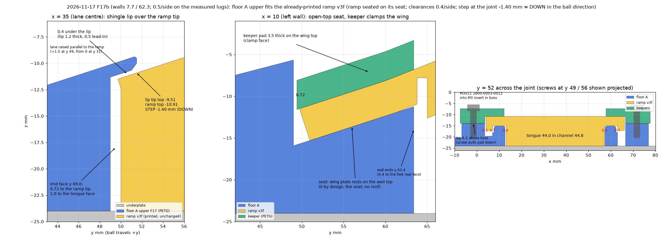
- Part: floor A upper, blue PETG, plate 37y (P2S, AMS slot 4), one body 251.0 x 195.8 x 41.0 mm. 4 walls, 20 % gyroid, no supports, no brim, bed 70 C. Est 4 h 09 min and 147 g (Bambu Studio showed about 4 h 36 min). It replaces plates 37 and 37u. The front bar (plate 37e) is unchanged.
- Open-top seat: the channel walls are cut down from y 49.0 to 63.4. The ramp wing drops in from above and rests on the wall tops. The slot roofs are gone.
- Clearances on Mark's measured ramp (tongue just under 44.0 mm, 62.2 mm across the lugs, 55.6 mm between them): tongue 0.4 mm per side; lugs to walls 0.5 mm; end face 0.72 mm to the ramp tip.
- Shingle lip and lane: the lane runs parallel to the ramp, 1.6 mm above it. A 1.2 mm lip overhangs the ramp tip from y 49.0 to 51.5. The step in the ball direction at the lip tip is 1.40 mm DOWN, so a ball never meets a step up.
- Keepers (2 printed parts): a pad on each wing top (outside the lane) and a leg over a boss, with a 0.2 mm design gap so the screws pull the pad onto the wing. 4 x goBILDA 2800-0003-0012 (M3x12) and 4 x M3 heat-set inserts 4.2 x 5.7. The ramp is not drilled.
- Result: Mark test-fitted the PETG floor with the yellow ramp: "Fantastic fit" (photo). The ramp seats with no step and nothing broke.
- Floor to underplate: the six inserts from below stay at (10,-50), (60,-50), (10,30), (60,30), (35,10), (35,40). The screws are now 6 x 2800-0003-0006 (M3x6) (B1).
Steps (2026-11-17)
- Press the 6 M3 inserts into the upper from below. Heat-set the 4 short (3.0 mm) inserts at y -125 from the z -24 face, gently, flush. Heat-set the 4 keeper inserts from the top of the bosses.
- Screw the front bar on from below with 4 x 2800-0003-0006. Check the strip top is flat.
- Test-fit one 1611-0514-4008 bearing in the boss pocket.
- Lay the floor on the underplate. Fit 6 x 2800-0003-0006 from below.
- Drop the ramp into the seat (B6), then fit the keepers with 4 x 2800-0003-0012.
Check: Ramp sits on the wall tops and on the underplate at the same time, no rocking. Step at the lip tip is down, never up. No bulge over the 4 short inserts. Not verified: the real thickness of the ramp wing plate; lip strength (1.2 mm PETG, 2.5 mm overhang printed without support, may droop slightly); the clamp force of the keepers; the lane slope change at y 31 (12 to 18 deg) is not simulated; the slicer files were not opened in Bambu Studio. A one-piece 259 mm version for the H2D exists (V7_floor_A_one_piece_259_2026-11-17f17_H2D.stl) in case this one fails; it is not needed now.
Superseded 2026-11-17: the upper part, plates 37 and 37u, and the screw lengths in "B3 update 2026-11-16" below (M3x10 for the floor screws, the closed wall slots). The front bar and its 4 short inserts still hold.
B3 update 2026-11-16: floor A split into an upper part and a front bar
The one-piece floor A (259 mm, then 251 mm) is superseded. It is now two printed parts joined at the plane z -24 (the underside of the main floor, which is the top of the underplate):
| Part | File | Size mm | Printer, material, plate | How it prints |
|---|---|---|---|---|
| Upper part (whole floor, windmill boss, lane, rails, kerb, the whole ball surface of the old strip) | V7_floor_A_P2S_upper_2026-11-16h.stl |
251.0 x 197.4 x 41.0 | P2S, PLA (Geeetech silk, slot 3), plate 37 | as in CAD, flat underside (z -24) on the bed, 4 walls, 25 % gyroid, no supports (bridges only), no brim |
| Front bar | V7_floor_A_front_bar_2026-11-16h.stl |
248.0 x 29.3 x 6.0 | Ender-3 S1 Plus, purple PLA, plate 37e | STL already flipped: z -24 face on the bed, counterbores up, no supports, est 2 h 44 min, 35 g |
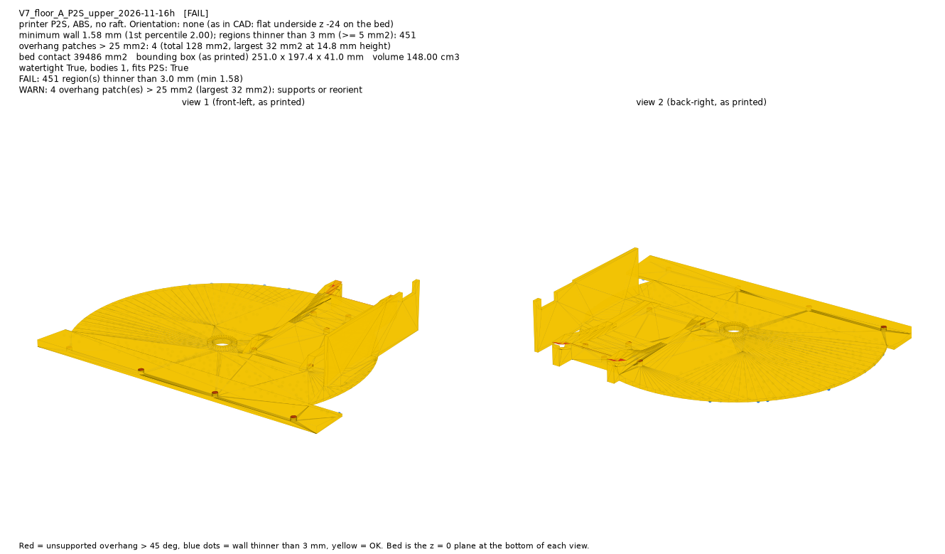
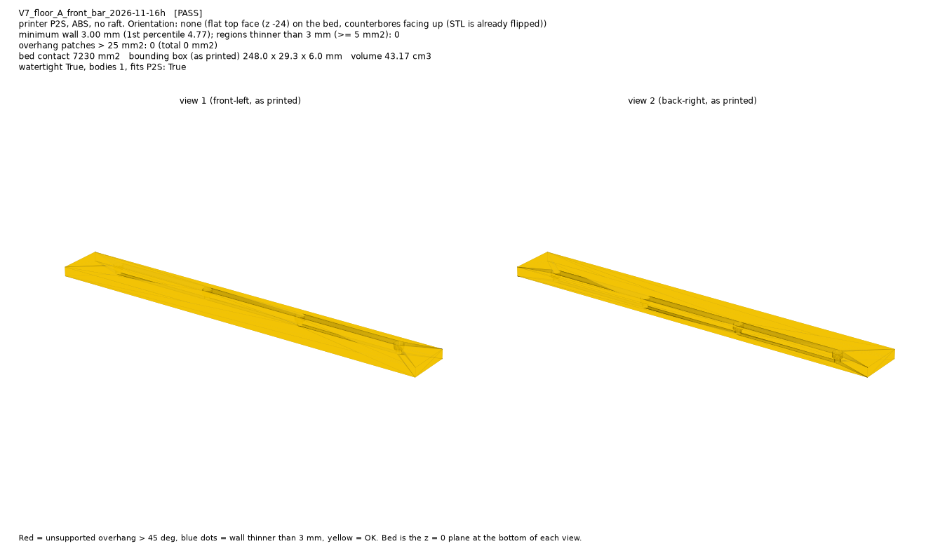
Why: a 259 mm floor does not fit the P2S or the K1C. Mark's rule: cut 8 mm off the +x end of the strip (the upper is 251.0 mm long) and split the strip's underside off as a bar. The upper keeps the whole top of the strip, so there is one ball surface and no seam. The bar front end is trimmed from y -100 to y -103.1, so it no longer overlaps the underplate front (the old 787 mm3 clash is gone, 1.99 mm gap).
Fixing the bar to the upper part: 4 x goBILDA 2800-0003-0006 (M3x6 socket head) into 4 x M3 heat-set inserts that are only 3.0 mm long.
- Positions: y -125, x = -104, -37, 29, 96, screws go up from the bar underside.
- Bar: 3.4 mm through hole and a 5.8 x 3.0 mm counterbore; the head sits flush at z -30 with 3.0 mm of bar floor under it.
- Upper part: 4.2 x 3.1 mm insert bores from the z -24 face (top of the bore at z -20.9). The M3x6 tip ends at z -21.0, flush with the 3.0 mm insert.
- Why 3.0 mm inserts: the strip is only 5.7 mm thick at its front edge and tapers (top z -18.3 falling to -22.0 at y -100). The usual 5.7 mm insert does not fit. A 3.1 mm bore leaves 1.52 mm of plastic cap above the insert (measured). The 3.8 mm short insert in the buy list would leave only 0.8 mm.
- Heat-set gently. Use a low iron temperature, push in slowly and stop when the insert is flush. If the 1.5 mm cap above bulges the ball surface, it is a ball-path defect: re-do that bore, do not file it down thinner.
- These 4 screws do not pass through the underplate (the strip is in front of the plate). An earlier note that they were M3x8 with only 1.65 mm engaged is void; they are M3x6.
Floor to underplate: the six inserts from below stay at (10,-50), (60,-50), (10,30), (60,30), (35,10), (35,40); the screws are now 6 x 2800-0003-0010 (M3x10) because of the 6.35 mm plate.
Not changed: the sloped slot in each rear channel wall (x 7..13 and 57..63, y 49.7..65, z -15.3..-6.2) is the locator for the printed ramp's foot; it is not filled. It shows 4 overhang patches of 32 mm2 on the gate; the slot is open at both x faces, so support there can be removed from the side. Pre-print gate: bar PASS (min wall 3.0); upper FAIL/WARN (min wall 1.58 at the 1.5 mm insert caps, 451 thin regions of which 373 are the fixed 2.0 mm floor between the ball surface at z -22 and the plate at z -24). Fits the P2S: 251.0 x 197.4 x 41.0.
Steps (2026-11-16)
- Print plate 37 (upper) and 37e (bar). Mark checks the upper in Bambu Studio first.
- Press the 6 M3 inserts into the upper from below (positions above).
- Heat-set the 4 short (3.0 mm) inserts at y -125 from the z -24 face, gently, flush.
- Screw the bar on from below with 4 x 2800-0003-0006. Check the strip top is flat (no bulges over the inserts).
- Test-fit one 1611-0514-4008 bearing in the boss pocket as before (B3 step 2 below).
- Lay the floor on the underplate and fit 6 x 2800-0003-0010 from below.
Check: Bar tight against the upper, no gap on the ball surface. No bulge over the 4 inserts. Floor flat on the plate, six screws pulled down.
Earlier text of this chapter (2026-11-15), kept for history
Where it disagrees with the 2026-11-16 text above, the 2026-11-16 text wins. Parts marked superseded are not used.
Superseded 2026-11-16: the one-piece floor A (plates 22, 23 and 25), the 6 x M3x12 and the 259 mm file below.
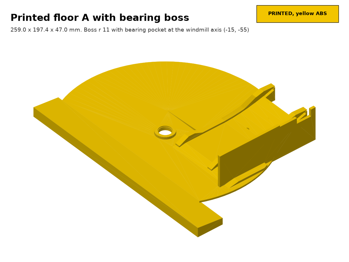
Parts: printed floor A (plate 25, Ender-3 S1 Plus, PLA test part; an ABS floor needs a new slice), 6 x M3 heat-set inserts from below, 6 x M3x12 screws (owned stock), 1 x flanged bearing 1611-0514-4008 (for B7).
New in this edition: a boss at the windmill axis (-15, -55): boss r 11 with its top at z -19, a bearing pocket r 7.05 and a flange recess r 7.6. The windmill axle runs in a bearing in this pocket (B7). The underplate is NOT cut under the boss.
- Press the six M3 inserts into the floor from below (soldering iron). Positions (x, y): (10,-50), (60,-50), (10,30), (60,30), (35,10), (35,40).
- Test-fit one 1611-0514-4008 bearing, flange up, in the pocket: it must drop in with the flange in its recess (do not force it). Take it out again.
- Lay the floor on the underplate. Its front edge meets the intake bar (y -132). The floor sits at z -30..17 in the model.
- Fit the six M3x12 from below through the 3.4 mm holes in the underplate.
Check (test plan 1.2): Floor flat on the plate, six screws pulled down. Feeler gauge at the lane and at the delivery pocket: lane surface within 0.5 mm of z -19.6 at the delivery seat (32.4 mm above the field). The right kerb has two steps (z 15.4 near y 8..31, z 8.3 near y 31..49) that were cut for the old gate servo. The one-servo drive does not use them; they are left as they are (the make sheet text says z 9.9: Check against CAD C8). Windmill boss: bearing sits flat, the boss top is at z -19.
FUSION VIEW F02 (placeholder): Floor A on the underplate, iso from front-left: pocket circle, lane, centring rails, right kerb, six screw positions, bearing boss
B4. Rails and kerb (fixed down with inserts)
B4 update 2026-11-15 (b, c) and 2026-11-16: rail arc 1 v3c and rail arc 2 v3, printed
- Rail arc 1 v3c (
V7_windmill_rail_arc_1_one_piece_foot_lintel_2026-11-15c.stl): the delivery-side wall now ends at 98.4 deg (the old sliver at 87.9..98.4 deg is gone and the cross channel face is the ball wall there). One piece, wall 5 mm, foot band with 3 insert pads, a lintel bridging the channel gap (needs small removable support on its underside). Gate min wall 2.69 mm (the walls between each insert hole and the ball face, accepted). - Rail arc 2 v3 (
V7_windmill_rail_arc_2_kerb_foot_pads_2026-11-15b.stl): solid kerb, foot band r 121..131 and two pads; gate min 2.93 mm. - Printed on plate 34 (K1C, yellow ABS): finished 100 % in 3 h 43 min with no printer errors on 2026-11-16. Fit not yet checked. Plate 27 and the 15b arc 1 are superseded.
- Fixing: 3 + 2 M3 heat-set inserts (4.2 x 6.2 in the boss) as before; the screws are now 5 x 2800-0003-0008 (M3x8) from below through the 3.175 mm 6061 plate (2026-11-17, U1; they were M3x12 for the polycarbonate plate), 4.8 mm engaged. Hole positions are unchanged (arc 1: (-58.72, 58.90), (-95.04, 37.07), (-121.70, 4.15); arc 2: (105.50, -74.09), (101.67, -90.67)).
Superseded 2026-11-16 where it differs: arc 1 (joined, plate 27) is replaced by v3c; the M3x8 screws are now M3x12.
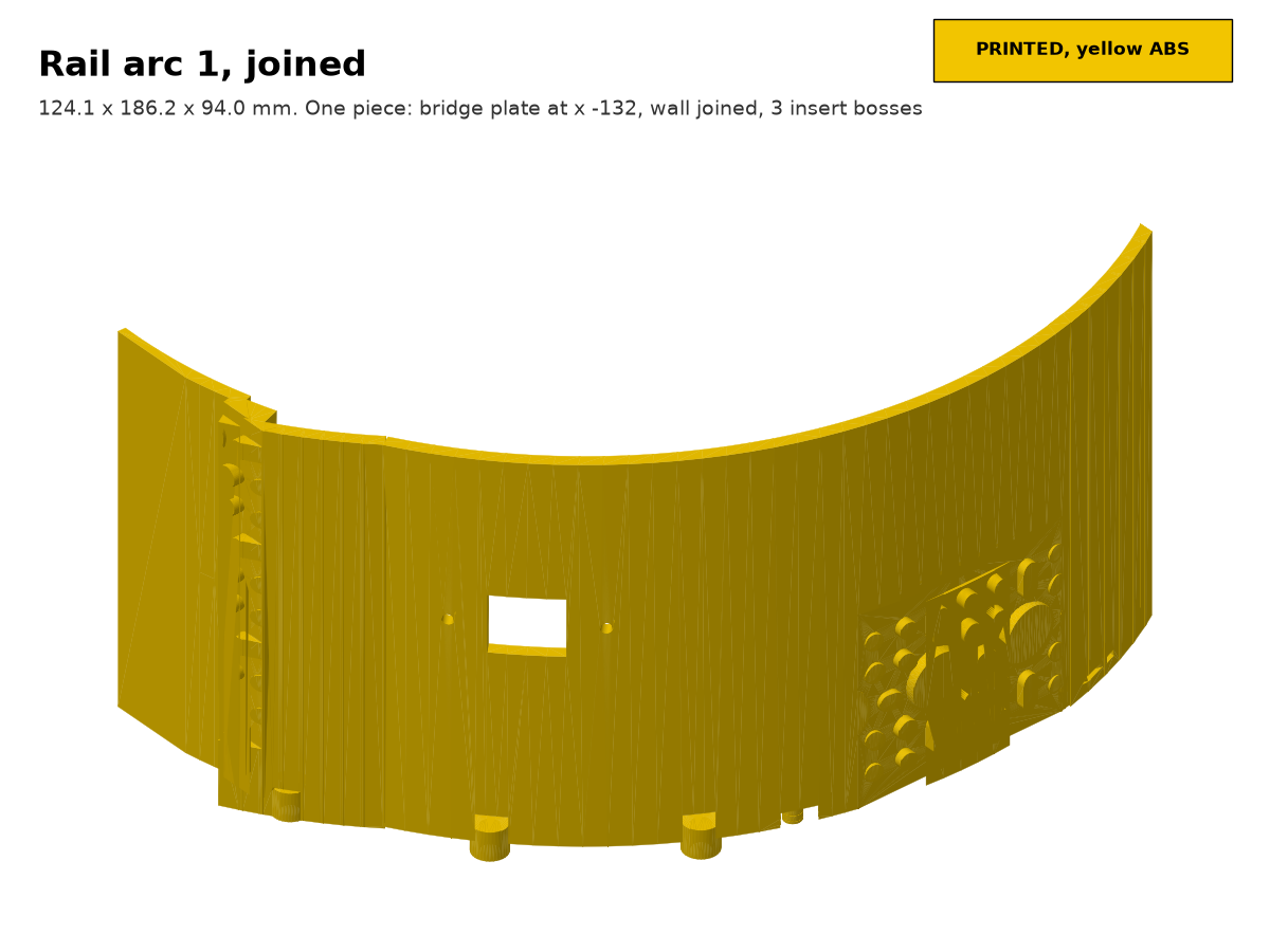
Parts: rail arc 1 with delivery-side wall (105..195 deg, flared lead-in, wall 88..105 deg, now ONE piece), rail arc 2 lower kerb (front right, top z 17, now SOLID), colour sensor shelf with back plate (see B11). Both are printed on plate 27. The rail is r 117..120 about the windmill axis (-15, -55). 5 x M3 heat-set inserts and 5 x M3x8 screws (owned stock).
What is new:
- Fixing. Each arc has insert bosses (OD 8 x 7 mm, z -24..-17) on the outside of its foot at r 122: three on arc 1 (at 111, 131 and 151 deg about the windmill axis) and two on arc 2 (at -9 and -17 deg). Each boss has an M3 insert hole 4.2 x 6.2 mm opening at the underside. The bosses stay outside r 120, so they do not touch floor A (r 116).
- Arc 1 is one piece. The old arc 1 had two parts that touched only along a line at x -132, y -55 (the flat cut for the chassis channel is tangent to the inner wall, so the wall had zero thickness there). A 1 mm bridge plate (x -132..-131, y -75..-35) now joins them, and the delivery-side wall, which was a loose lump, is joined by a connector (r 118.5..126.5, 103.5..108.5 deg). Arc 1 has no openings in the wall except the sensor window and its two 2.5 mm pilot holes.
- Arc 2 is a SOLID wall. The old kerb had a slit and a window with a post. The new one is the old section thickened outward to about 5 mm (the inner ball face is unchanged), z -24..17, with floor A cut out where they overlap. There is no opening.
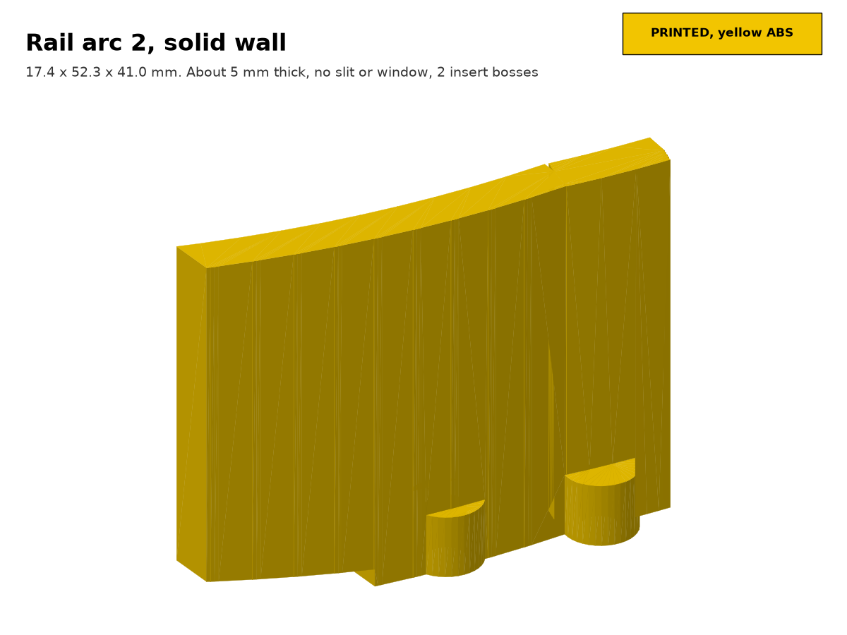
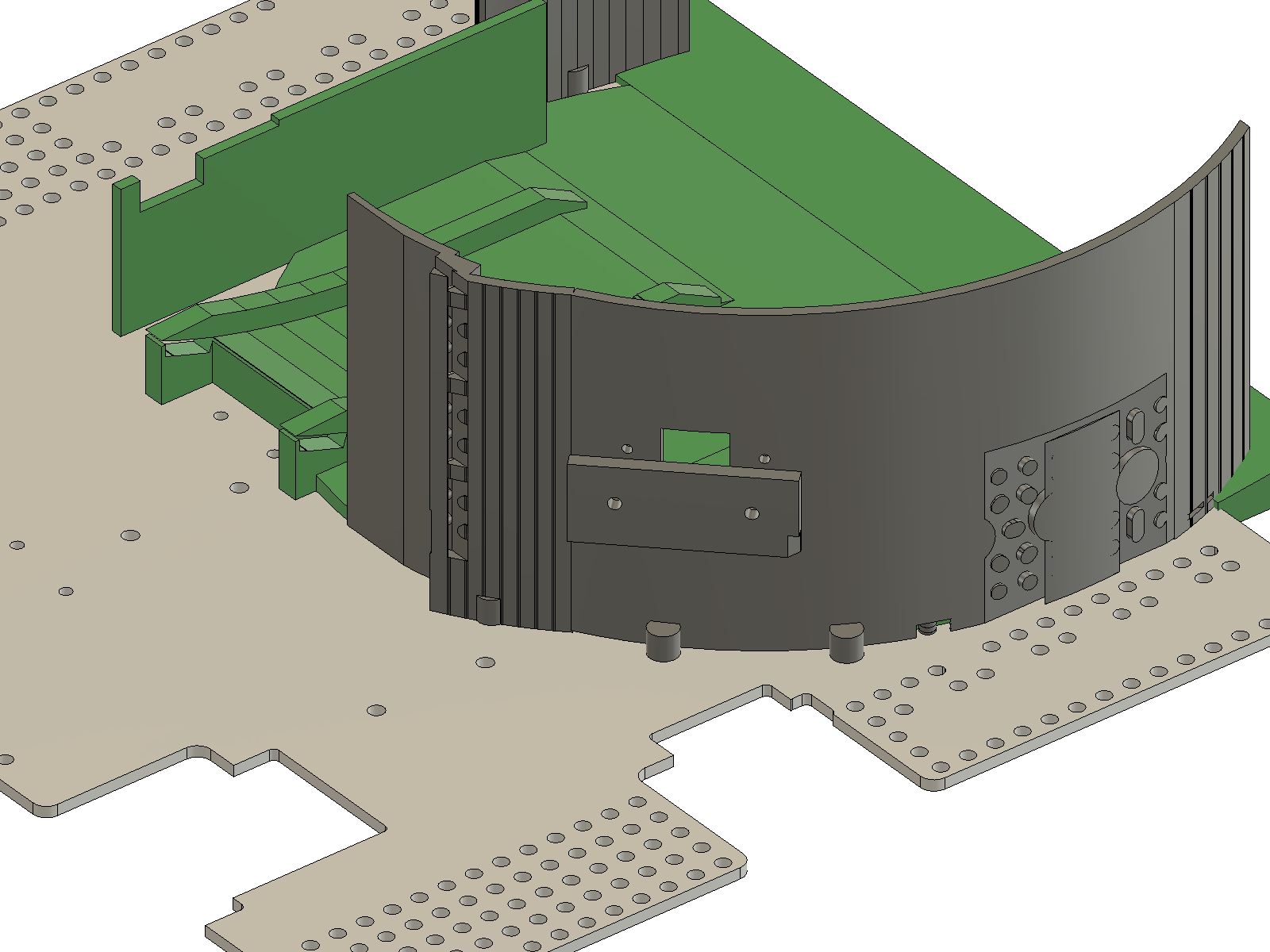
- Press the 5 M3 inserts into the bosses from below (soldering iron, perpendicular, flush with the underside).
- Lay arc 1 on the underplate with its three bosses over the three new plate holes (-58.7, 58.9), (-95.0, 37.1), (-121.7, 4.2). Lay arc 2 with its two bosses over (105.5, -74.1) and (101.7, -90.7).
- From below, fit one M3x8 screw into each insert through the 3.4 mm plate hole. Pull down snug, not tight (the plate is 3.2 mm, the insert 6.2 mm deep).

Check: The delivery-side wall starts at 88 deg and does NOT block the lane (the first drawing of it did). Each arc is down on the plate with no rocking. Arc 1 is one piece: no crack at x -132. Arc 2 has no slit or window. A ball runs along both arcs with no step at a joint.
FUSION VIEW F03 (placeholder): Rail arcs and kerb on the floor, top view, with the 4 pocket positions marked
B5. Flywheel tower (lowered 8 mm) and carriage
What is lowered by 8 mm (one hole pitch on the uprights): flywheel Hogback, its motor, hub 1310-0016-4008, motor channel 1120-0002-0072, quad block 1201-0043-0002:7, side plates C (both), hood H, flywheel discs, the whole V4 carriage four-bar (ground plate, carriage plate, links A and B, carriage bar, stops, servo bracket and posts), carriage servo 2000-0025-0003, stop plates, K5 hardware and their screws. The uprights, tube and mounts stay where they are. The windmill beam and its quad block do NOT move.
Parts to make (mill 3 mm 6061): carriage ground plate, carriage plate, link A, link B, servo bracket, stop plates (files cad/cut_files/carriage_*.step, link_A/B_3mm.step). No record that they were made.
Steps (carriage layout from V4 notes, which V7 keeps):
- Ground plate on the right upright's +x face. Right upright is then bolted to the base (stock step 40).
- Carriage bar (5-hole channel sawn to y > -30) on the carriage plate; two 45 mm links on four pins (a parallelogram, ground joints -26.3..0 deg, carriage joints 0..+26.3).
- 1:1 motor on its quad block and 2-hole channel hangs from the bar. Do not fit the stock screws that tie the block to the channel.
- Servo bracket on four 6 mm posts; Speed servo 2000-0025-0003 with its spline in link A's 6.1 mm hole; two hard-stop posts at the ends of link A's swing; stop plates (3 mm 6061, 25 mm slot) at x 140..143.
- Hogback on the 1:1 shaft with the 1 mm gap (Figure 55-A), plus the two 64 x 4 mm steel discs (about 100 g each, x 15..23). Fix them with 4 x M4x20 through both discs into the hub web (from the BoM; the CAD draws no fixing: Check against CAD C12).
- Plates C and hood H one pitch lower (stock steps 41 and 57).
Poses to set in software later: small ball theta 0.5 deg with a 3 mm small-ball stop, large ball 22.5 deg.
Check: Carriage moves to both stops and holds each. Hogback turns freely. Nothing touches the ramp area (the ramp is not fitted yet).
FUSION VIEW F04 (placeholder): Carriage four-bar and flywheel from +x, with the 8 mm lowering marked
B6. Printed ramp (v3f with gussets; 6 mm sheet, side blocks)
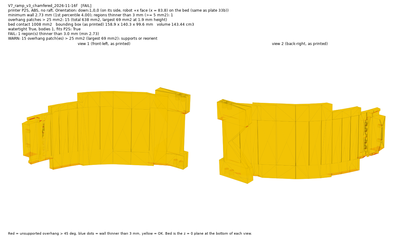
B6 update 2026-11-16: printed ramp v3f (44 deg gussets), printed on its side
The 6 mm ramp (plates 20, 28), ramp v3 (plate 33: supports toppled) and the 33b print (the top lip printed in mid-air) are superseded. Mark's decision: the ramp stays flat with kerbs, with 44 deg gussets on both sides.
- File:
V7_ramp_v3_chamfered_2026-11-16f.stl, plate 33c, P2S, Polymaker ABS-MF yellow (AMS slot 2), on its side with the +x face down (down:1,0,0): ball surface vertical and smooth, layer lines along the ball path. 6 walls, 35 % gyroid, grid supports from the plate only, 12 mm brim. Estimate 4 h 40 min, 126 g (Orca proxy). - What changed (material added only, nothing removed): a 44 deg gusset under each rear side block (mirrored about the sheet centre x = 35, so the two overlap into a V), and a pedestal under the sheet edge on both sides. The ball surfaces, running surface, kerb heights, holes and screws are untouched. Body 99,052 to 143,431 mm3, bbox unchanged. Overhang patches 32 to 15 (1,923 to 638 mm2). Min wall 2.73 mm (the pre-existing M4 insert wall).
- Still overhanging (Mark's call): 9 patches of 377 mm2 at 1.9 mm above the bed (setting the pedestal caps to 83.8 mm removes them but leaves 0.2 mm to the side plate), and 6 patches of 346 mm2 under the foot (no room for pedestals). Put grid support there, low and straight over the bed.
- Print history: plate 33 failed (slim tree supports toppled); 33b failed (top lip in mid-air); the first 33c attempt lost adhesion (the part moved). Mark washed the plate with soap and put on fresh glue and is reprinting the same file.
- Hardware (updated 2026-11-17): 2 M3 inserts in the foot at (25,57) and (45,57) with 2 x 2800-0003-0008 (M3x8) from below through the 1/8 in plate (U1; were M3x12); 4 M4 inserts in the side blocks with 4 x 2800-0004-0010 to the plates C.
- 2026-11-17: the ramp v3f is printed (plate 33c, Mark: "looks great") and is NOT reprinted. It sits in the open seat of the new floor A upper (B3). Two printed keepers hold the wing with 4 x 2800-0003-0012. Measured on the real part: tongue just under 44.0 mm, 62.2 mm across the lugs, 55.6 mm between them.
- Not verified: slicer preview, print time and weight (+45 %), warp of the 100 mm tall wall, ball flight over the new rear gusset tops (kept 3.4 mm or more below the lane tangent, not simulated).
Earlier text of this chapter (2026-11-15), kept for history
Where it disagrees with the 2026-11-16 text above, the 2026-11-16 text wins. Parts marked superseded are not used.
Superseded 2026-11-16: ramp 6 mm (plates 20, 28), ramp v3 (plates 33, 33b).
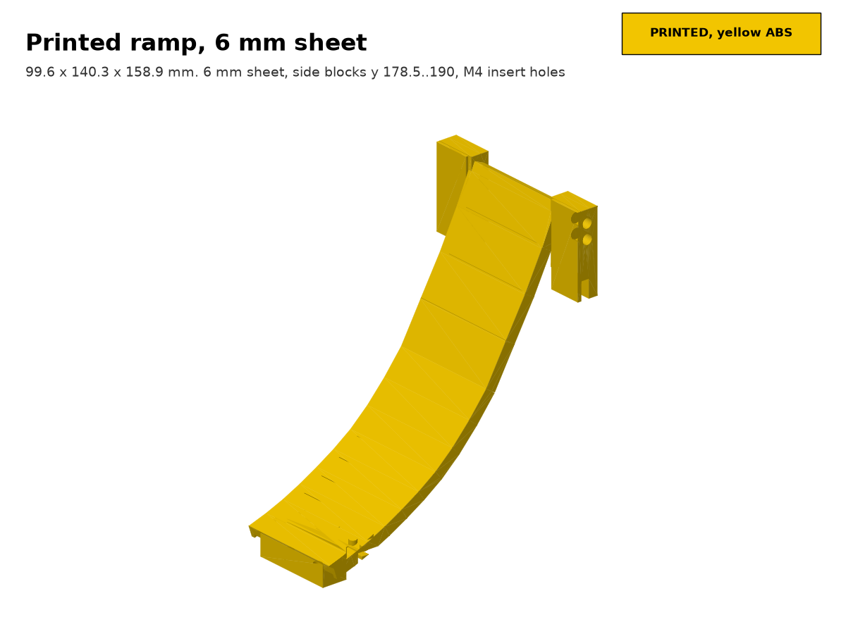
Parts: printed ramp (plate 28, P2S, one print). 2 x M3 inserts in the foot at (25,57) and (45,57); 4 x M4 inserts in the side blocks. Screws: 2 x M3x12 into the foot (through the underplate), 4 x M4x10 (2800-0004-0010) to the plates C at their own holes (z 120 and z 128, inside the side blocks).
What is new: the sheet is 6 mm (it was 4 mm). The extra material is only underneath; the top (ball) surface is unchanged to within 0.01 mm. The side blocks now run from y 178.5 to y 190 (the front part is only x <= 4.9 and x >= 65.1 for y 178.5..180, so the lane edge strip is untouched). The top of the blocks is z 134.92 as before and the M4 holes are re-cut with at least 2.5 mm of wall round every insert (the web between the z 120 and z 128 holes is 2.4 mm, fixed by the plate hole pitch). The ramp is trimmed where it would hit the cross channel and floor A. The ramp is 99.6 x 140.3 x 158.9 mm.
Clearances in the model: side blocks to side plates C 0.53 mm, ramp to flywheel 88 mm. The robot rear is at y 190 (the channels reach 192.0; the 18 in limit is 197.2).
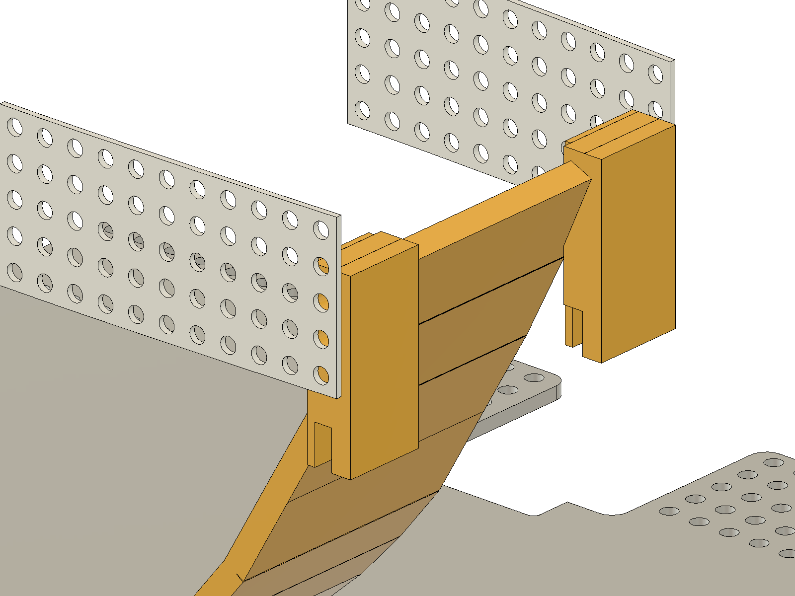
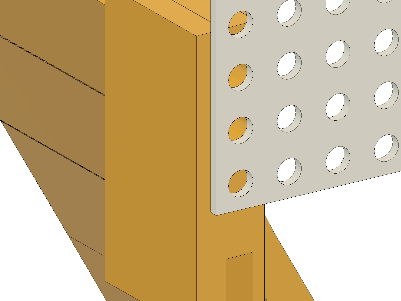
- Press the inserts in (2 in the foot, 4 in the side blocks).
- Lay the ramp between the rails with its solid foot (y 50..64) on the underplate and its underside on the base channel.
- Fit the screws. Do not overtighten the M4 into the side-block inserts.
Check (test plan 1.3): No rocking. No gap at the lane-to-ramp joint: step less than 0.3 mm (feel with a fingernail). The side blocks lie against the plates C with a hair of clearance (about 0.5 mm in the model): do not force them. Nothing on the ramp reaches past y 190 at the rear. The side blocks do not touch the shot path.
B7. Four-vane windmill (one-piece printed rotor; bottom hub, axle and bearing)
B7 update 2026-11-15 (b, c): the printed rotor is ONE piece
2026-11-17: the printed rotor on plate 35k is GREY, so it is a stand-in. Mark will replace it with a part that has aluminium fins. Print status: printed. The windmill bottom bearing was turned 30 degrees about its axis in the CAD to clear the hex of the 16 mm stub (clash 12.8 mm3 to 0). goBILDA does not stock a 16 mm REX shaft (the shortest is 2106-4008-0240, 24 mm): the stub is still a stand-in and the decision is open.
The current build uses the one-piece printed rotor v3 (V7_windmill_rotor_ONE_PIECE_3mm_print_2026-11-15c.stl, plate 35, P2S, ABS). The bolted-vane windmill below (two printed hubs, four milled aluminium vanes, 8 cross-bolts) is superseded: it is kept in the CAD as a hidden fallback ("WINDMILL ROTOR aluminium vanes (final)"; its 8 x M3x16 show as hidden in the screw list), and its hub STLs are not printed.
- Body: hubs and 4 vanes in one body, vanes 3.0 mm and solid everywhere (the vane slot is filled: nothing uses it), 106,318 mm3 (about 110 g ABS). Top hub keeps its 4 x M4 on a 16 mm square and a 7.2 mm across-flats hex socket for the 8 mm REX stub; bottom hub runs on the 8 mm axle in the bearing boss on floor A (B3, bearing 1611-0514-4008).
- Magnet posts: 4 posts on the vane tops (base 3 mm at z 72.5, 45 deg flare, column to z 85.7, 12.2 x 12.2 plan) each with a D6.1 x 3.1 pocket for a 6 x 3 mm NdFeB magnet at r 30; wall around each pocket 3.05 mm. The old clips and dowels are not used.
- Print right side up (bottom hub on the bed) because the posts reach 9.2 mm above the top hub. Tree supports (auto), 6 walls, 30 % gyroid, brim 6, 34 small overhang patches (40-63 mm2, none over 100 mm2). Gate: WARN only, min wall 3.00 mm, watertight, 1 body, bed contact 626 mm2. The top hub servo face is the last layers, so check its flatness before fitting the servo hub.
- Sweeps: 72 poses (every 5 deg) against 591 bodies: 0 hits. Stop every index within +-1 deg and keep the blade parked while the rotor turns (counter-clockwise offsets of +1 to +4 deg hit a vane from blade travel 55).
- Vane thickness in the sim: 3.0 mm vanes scored the same 114/120 as 1.6 mm (round 39): neither helps nor hurts.
Steps (replace the cross-bolt steps below)
- Print plate 35. Remove supports from the slots and the hub undersides. Check the bottom hub bore and the servo face.
- Press the 6 x 3 mm magnets into the 4 post pockets (polarity as the hall switch needs: test with the REV-31-1462 before gluing).
- Fit the 8 mm REX stub into the top hub socket (confirm the 7.2 mm hex fit), fit the axle and the flanged bearing in the boss as in B3, then the rotor.
- Turn the rotor by hand through 360 deg: it clears the rails, floor, blade and gate arm.
Check: Rotor turns freely. Hub clearance to the floor boss about 1.0 mm. Vane notch clearance to the boss about 0.5 mm. Magnets flush at the top of the posts.
Earlier text of this chapter (2026-11-15), kept for history
Where it disagrees with the 2026-11-16 text above, the 2026-11-16 text wins. Parts marked superseded are not used.
Superseded 2026-11-15 (b, c): the bolted-vane build below, plate 26 hubs and the aluminium vanes (fallback only).
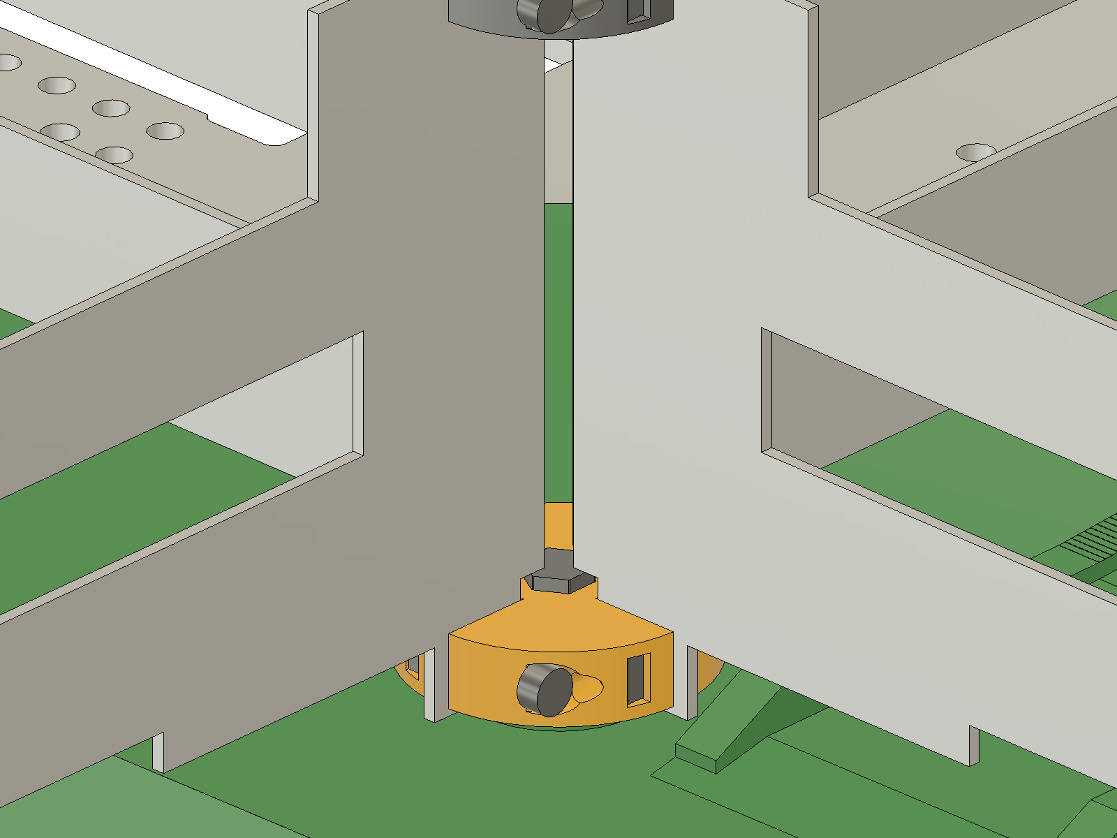
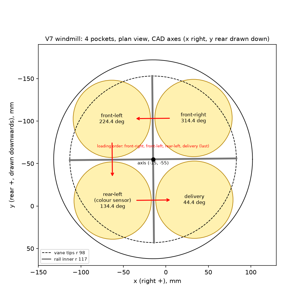
The windmill has 4 pockets at 44.4 (delivery), 134.4 (rear-left), 224.4 (front-left), 314.4 (front-right) deg about the axis (-15, -55). Team rule: it turns clockwise seen from above, and the delivery (shooting) pocket is the last pocket a ball reaches. One index is 90 deg. Loading order: front-right (314.4) -> front-left (224.4) -> rear-left (134.4) -> delivery (44.4). The angles decrease, which is clockwise seen from above (front at the bottom of the page, rear at the top), as the team rule requires.
What is new: the rotor is now a rigid cage. A top hub (z 64.5..76.5) and a bottom hub (z -18..-9) both hold all four vanes, each vane held by one M3 cross-bolt per hub (8 in all). The bottom hub sits on an 8 mm REX axle that runs in a flanged bearing in the boss of floor A (B3), so the rotor is steadied at its foot as well as driven from the servo at the top. The axle line is concentric with the servo spline to 0.006 mm.
Parts
| Part | Qty | File or part number |
|---|---|---|
| Top hub, printed (plate 26), OD 36 x 12, 4 vane slots, 4 cross-bolt holes and nut slots, M4 pattern for the servo hub | 1 | V7_windmill_top_hub_OD36_cross_bolt_slots_2026-11-15.stl |
| Bottom hub, printed (plate 26), OD 36 x 9, 4 vane slots, 4 nut slots, 7.2 mm hex socket | 1 | V7_windmill_bottom_hub_OD36_x9_2026-11-15.stl |
| Vane, 6061 1/16 in, with notch and 2 holes, at 89.4, 179.4, 269.4, 359.4 deg | 4 | vane STEPs V7_windmill_vane_N_milled_notch_holes_2026-11-15 |
| 8 mm REX shaft 16 mm (2106-4008-0160, confirm SKU, or cut from a longer shaft) | 1 | buy |
| Flanged bearing 1611-0514-4008 (8 mm REX bore) | 1 | buy; sits in the floor A boss, flange up |
| M3x16 socket screws and M3 nuts | 8 + 8 | owned stock (4 per hub) |
| Windmill Torque servo 2000-0025-0002 in its Compact ServoBlock | 1 | kit |
| Hanger plate 3 mm and spacer 2.4 mm | 1 + 1 | carried over |
| Magnet clip (4), 6 x 3 mm magnets, 3 x 6 mm dowel pins | 4 | carried over |
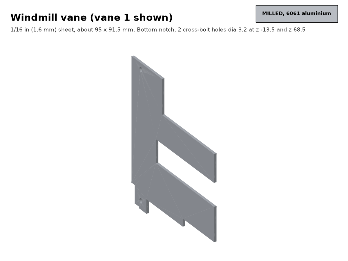
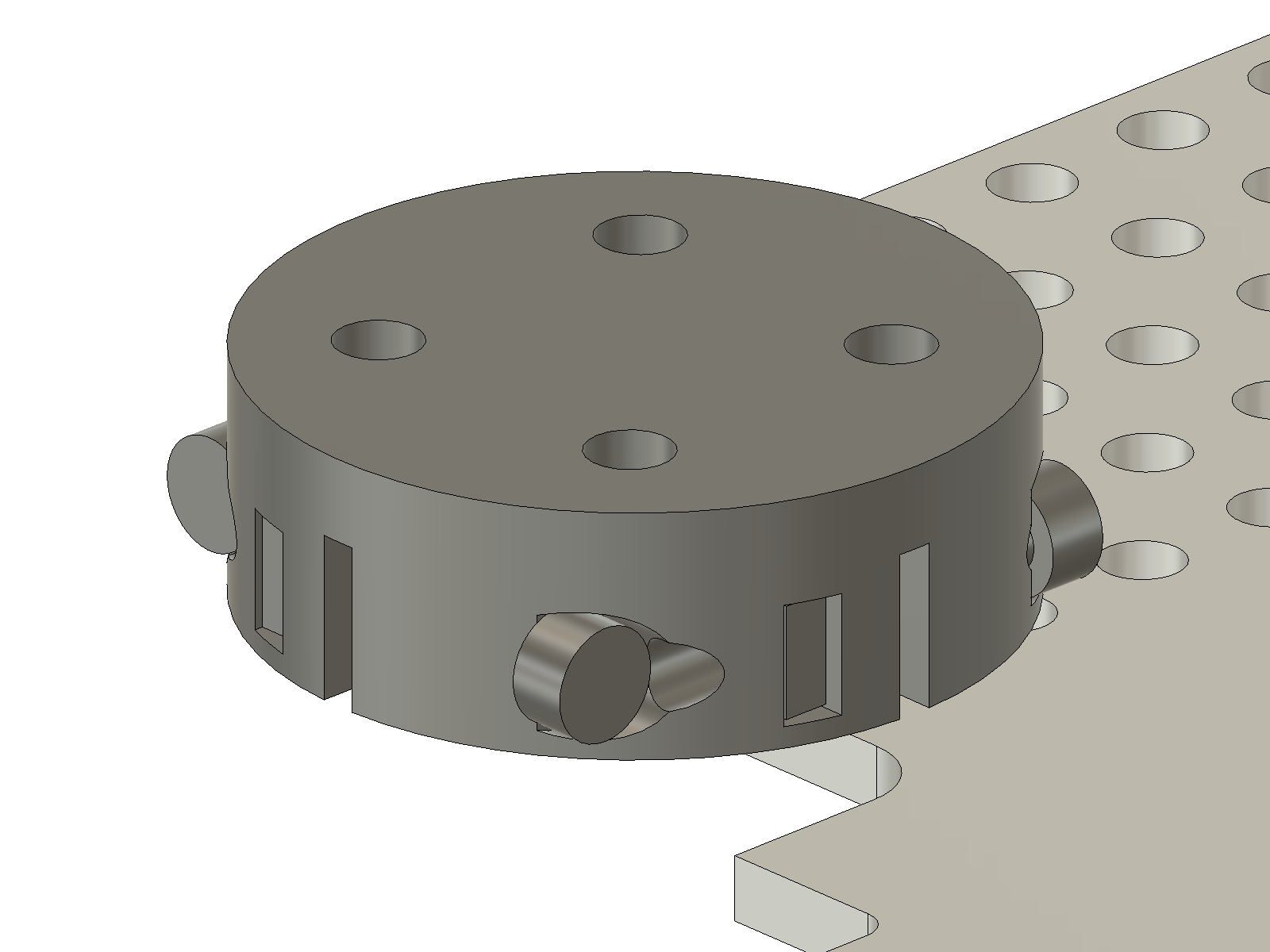
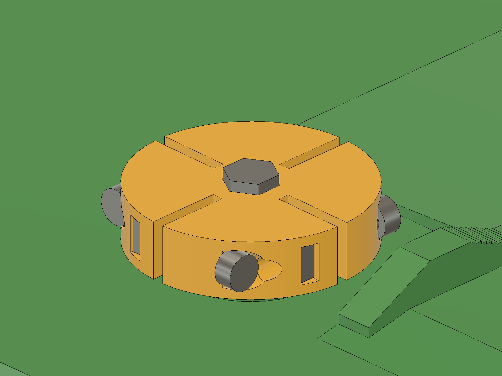
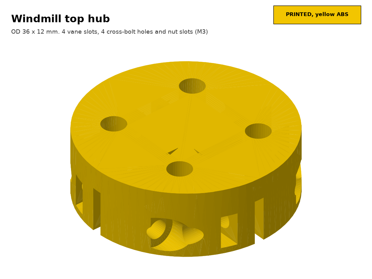
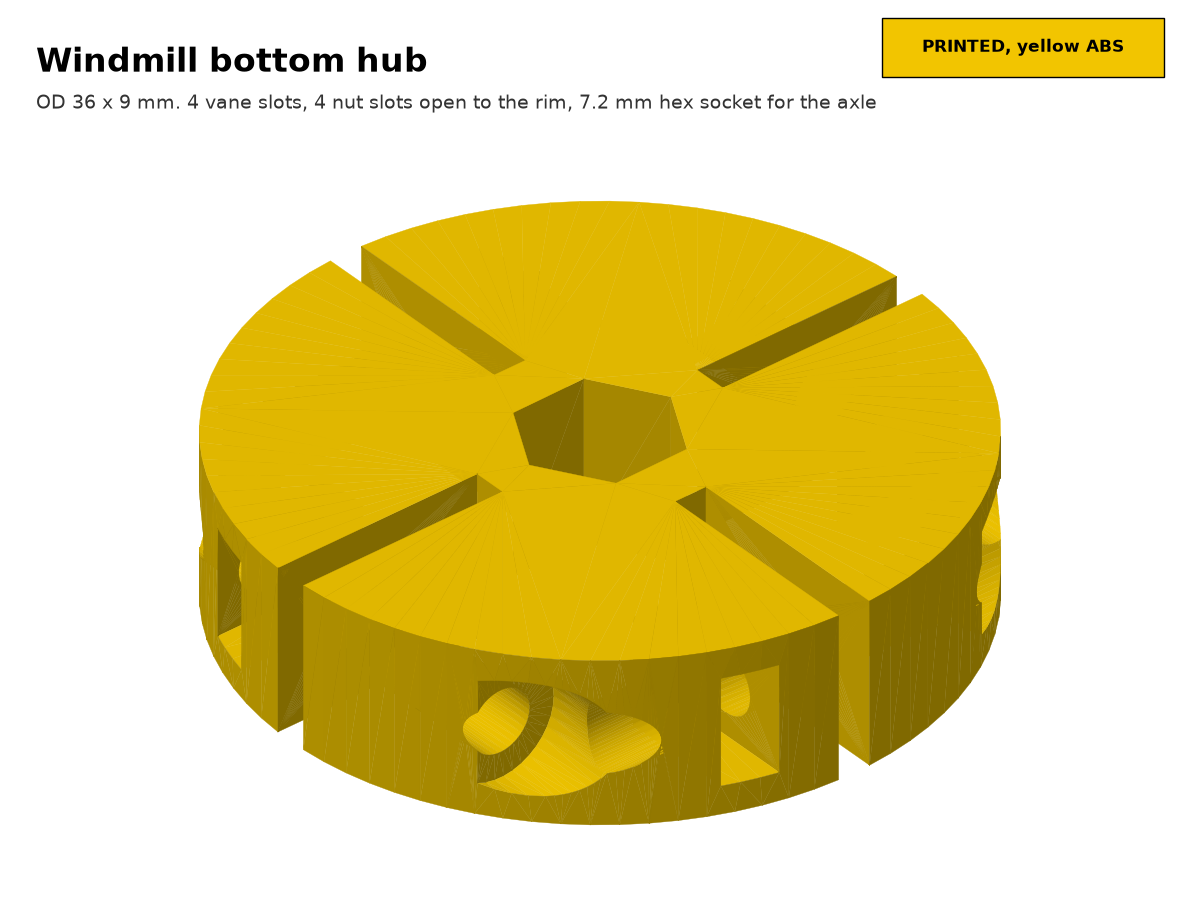
Vane facts. Outline: r 3..20 z -19..72.5; r 20..38 z -10..72.5; r 38..62 z -10..50; r 62..98 z -5..50. Pusher slot z 17..32 from r 31 to the tip. The bottom corner has a notch (r 3..11.5 by z -19..-18, and r 3..6.7 up to z -6.5) so the vane clears the axle and the boss (vane notch to boss 0.5 mm, hub to boss 1.0 mm). Each vane has two 3.2 mm holes at r 13.8, at z -13.5 (bottom hub) and z 68.5 (top hub). In the robot frame the bottom-hub holes are at (-14.86, -41.20), (-28.80, -55.15), (-15.15, -68.80) and (-1.20, -54.86) for vanes 1 to 4.
The cross-bolt. The bolt lies along a tangent at r 13.8, across the vane. Hub side one has a 3.4 mm clearance hole and a 6.2 mm counterbore for the head. Hub side two has a nut slot (2.7 x 6.6 x 5.9 mm) that is open to the rim, so the M3 nut slides in radially.
- Press the bearing (1611-0514-4008) into the floor A boss pocket, flange up, flange in its recess. It rests on the underplate. The underplate has no hole there: do not cut one.
- Bench: slide the 8 mm axle into the bottom hub's hex socket (test the fit first: the socket is drawn 7.2 mm across the flats, the real fit is not yet confirmed, see Check against CAD C19). The axle stands about 5.4 mm below the hub and 1.6 mm above it.
- Bench: push each vane, notch down, into a bottom-hub slot (1.8 x 8 mm). Put an M3x16 through the counterbored side, the vane hole and the hub, and slide an M3 nut into the open slot on the other side. Tighten snug. All four bolts go the same way round.
- Bench: slide the top hub over the four vane tops and bolt each vane the same way (z 68.5).
- Fix the top hub to the servo hub 1910-0025-0812 with the 4 x M4 (pattern to be checked against the real hub: Check against CAD C14).
- Hang the servo on the beam through the hanger plate and spacer. Beam is at x -64..-52, y -80..64, z 96..144. As the rotor comes down, the axle must drop into the bearing in the boss. If it does not find it, stop and report: do not force.
- Clip magnets on the vane tops (carried-over clips). Fit on the new vanes is NOT confirmed (Check against CAD C14).
Check: Turn the rotor by hand a full circle: vane tips (r 98) clear the rail (r 117), the floor and the lane; the notch and the bottom hub clear the boss; the bearing turns freely and the axle does not bind. Bolts tight, nuts do not turn. Hub at z 64.5..76.5 (top) and z -18..-9 (bottom). A vane does not move in its slots when pushed. (The CAD sweep of the saved model is clean for 0 to 110 deg in 5 deg steps; 115 to 355 were swept before the last small edit only.)
FUSION VIEW F05 (placeholder): Windmill rotor in place, top view, vane tip circle and rail
B8. One servo for the blade and the gate: build
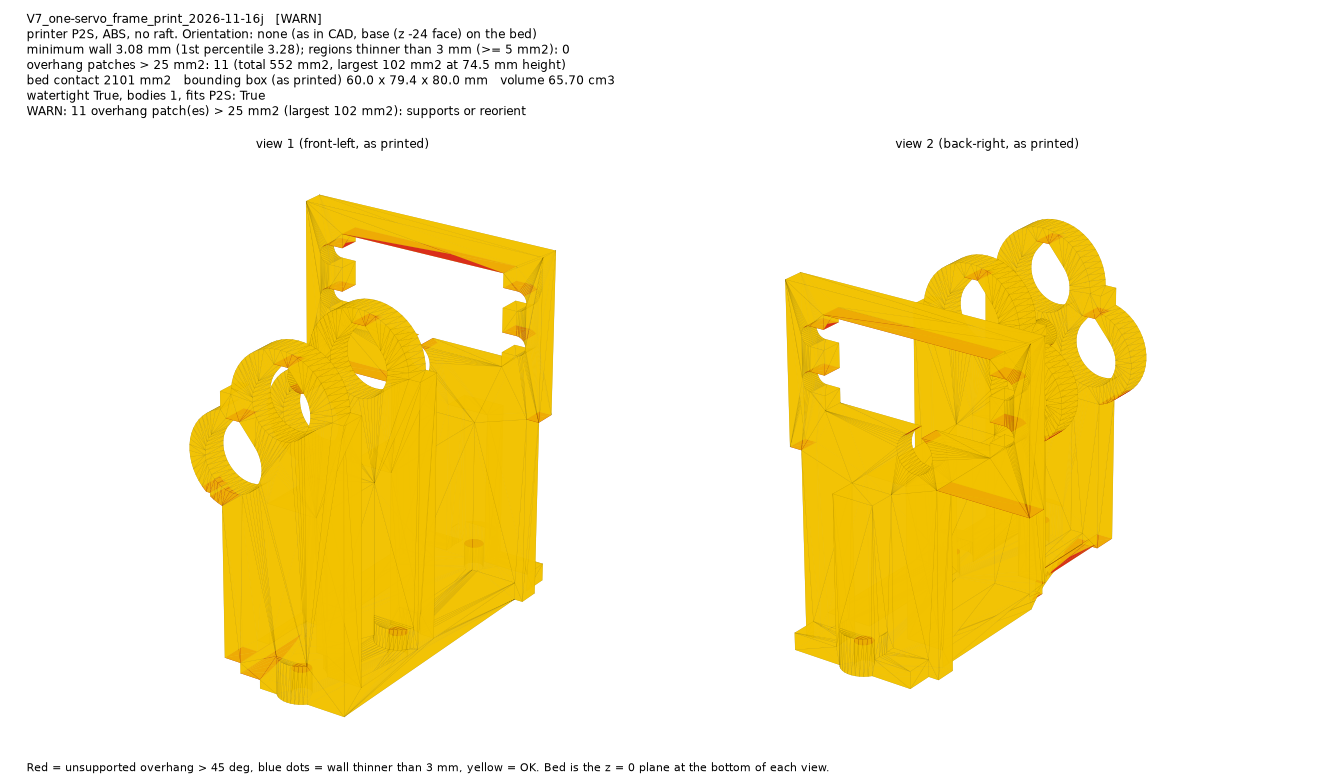
B8 update 2026-11-17: Axon MAX servo, real vendor parts, bearing counterbores
Everywhere in this chapter, "Torque servo 2000-0025-0002" on the blade-and-gate frame now means the Axon MAX MK2, 2004-0025-0002 (decided late 11-16, work order 16r). The body is 40.0 x 20.0 mm. The ear pattern is the same (U-slots at 48 x 10 mm), the spline sits on the same axis, and the ear flange is thinner (2.5 mm, was 3.66 mm). The frame fits as is.
- Frame: the printed frame 16j on plate 38p (yellow ABS, P2S) is printed and still usable. No reprint is needed for the servo. The servo plate window (40.6 x 20.6) takes the 40 x 20 core. The ear holes at x 72 and 120, z 35 and 45 match the Axon slots. The 4 ear screws stay 2800-0004-0012 with 4 plain M4 nuts, moved 0.1 mm to sit on the thinner ear.
- Servo clearances (CAD): servo to coupler 0.4 mm, gate shaft 1.0 mm, gate arm 2.7 mm, side plate 7.5 mm (was 0.8). The connector stub is x 114..121.5, y 43.8..48.3. Keep x 121..130.5, y 44..64 free for the cable.
- Bearing counterbores (new, from the real 1611-0514-4008 shape). The real bearing has a 1 mm flange (O15.0) and the frame pockets were plain O14. Each of the 4 bearing seats needs a counterbore from the OUTER face of its plate: dia 15.6 mm, flat floor 2.2 mm below the plate face (+-0.1), concentric with the existing 14.1 mm bore. The flange must sit flat with its outer face 1.0 mm below the plate face. The flange goes outward on both plates (front plate toward -y, rear plate toward +y).
- Hand fix for the printed frame (plate 38p): use a piloted counterbore or a 16 mm end mill in a drill press, frame clamped, depth stop. A plain Forstner has no centre to bite (the bore is open): use a 14 mm rod or a spare 1611 bearing as a pilot. Cut in 0.5 mm steps. Positions in frame coordinates: gate bore x 94.0 / z 25.5, blade bore x 106.0 / z 40.0, one counterbore on each plate per bore. Wall to the gate boss stays 3.0 mm, to the blade boss 4.3 mm.
- Or reprint:
V7_one-servo_frame_print_2026-11-17s3.stlhas the counterbores (no plate made yet). - Blade shaft is now 2106-4008-0520 (52 mm, was 56 mm). The real 4001-0025-4008 coupler is 17 mm long and its bore bottoms out at y 2.3, so a 56 mm shaft would have sat 3.7 mm inside solid metal. The gear end of the shaft is unchanged. The BoM FINAL still lists 0560 for this line: fix it before you order. The gate shaft stays 2106-4008-0960.
- Frame feet screws: 3 x 2800-0003-0008 (M3x8) (was M3x10), 4.8 mm engaged in the inserts, 0.9 mm spare under the insert top (U1, B1).
- Carriage servo spacers: printed with plate 38p (2 spacers). Fit 4 x 2800-0004-0020 as before.
- Electrical: the Axon MAX stalls 4.0 A at 6 V (3.6 A at 4.8 V). FTC rule R502 limits 4 A at 6 V. Mark ruled the Axon legal.
- Not verified: the 11-15 torque, jam and lock-load numbers were not re-run for the Axon stall torque. Spline engagement in the coupler (tip within 0.1 mm of the old one). Only the connector stub is modelled, not the plug or the 300 mm lead.
Steps (2026-11-17), added to the steps below
- Counterbore the 4 bearing seats (or print the s3 frame). Test-fit a bearing: flange flat, 1.0 mm below the face.
- Fit the Axon MAX to the servo plate with 4 x 2800-0004-0012 and 4 nuts. Check the nuts clear the plate.
- Fit the 4001 coupler and the 52 mm blade shaft. Do not tighten the coupler yet (phase, B8 step 8 below).
B8 update 2026-11-16: frame walls, servo ear screws, carriage servo spacers
One-servo frame V7_one-servo_frame_print_2026-11-16j.stl (60.0 x 79.4 x 80.0 mm, 65.7 cm3, P2S, yellow ABS, printed as in CAD with the base down). It supersedes the 2026-11-15 and 16i frames (the 2026-11-15 frame was printed on plate 24: reprint the frame; the gears, blade and gate arm of plate 24 are unchanged). Gate WARN: min wall 3.08 mm, 0 thin regions, 11 overhang patches of 552 mm2 and none in a bore. Changes: the 4 bearing seats are plain D14.1 through bores with a 50 deg teardrop top (no support inside a bore); bosses grown so every ring is 3 mm or more; the 2 mm slab under the gate built up to 5 mm; each servo ear hole is slotted open into the servo window (the strip to the window cannot be 3 mm), and the servo plate's right edge extended from x 123 to 126. Bearing retention in the through bores is a press fit (not verified; the 1611 flange is not modelled).
Fixings (2026-11-16)
| What | Part number and count | Notes |
|---|---|---|
| Frame foot to the underplate | 3 x 2800-0003-0008 (M3x8; was M3x10 for the polycarbonate plate, B1) into 3 x M3 heat-set inserts (4.2 x 5.7, bosses r 5.2) at (105.0, 33.0), (108.0, -36.0), (114.99, -11.42) | heads under the 3.175 mm plate (2026-11-17); 3 x 3.4 mm holes in the plate |
| Servo ears (servo 2000-0025-0002:2) | 4 x 2800-0004-0012 (M4x12) + 4 plain M4 nuts | ear hole axes at x 72.0 / 120.0, z 35 / 45; heads on the -y side; a plain 3.2 mm nut fits behind the 5 mm plate, a 4.9 mm nyloc does not |
| Windmill servo (:1) | 4 x 2800-0004-0008 + 4 x 2801 washers | already fitted, unchanged |
V4 carriage servo (2000-0025-0003:28) ear spacers. The servo's ear flange (x 163.45..167.9) sat in free air 10.3 mm in front of its bracket plate (x 152.1..155.1), so the screws would have held nothing. Fix: 2 printed C-spacers (V4_carriage_servo28_ear_spacer_A_y66_2026-11-16j.stl, ..._B_y113_..., 21.0 x 8.3 x 8.3 mm each, x- face down, bed contact 131 mm2, WARN min wall 3.04 mm, no overhangs), 8.3 mm thick from x 155.1 to 163.4, with a slot toward the servo body. The bracket plate also changes: 2 tabs (y 61.3..64.3 and 111.7..118.6, z 181.5..202.5) and 4 x D4.5 holes at the ear holes (y 66.59 and 113.31, z 187 and 197). Screws: 4 x 2800-0004-0020 (M4x20), heads on the +x side of the ears, tips 4.2 mm past the plate, with 4 nuts (not modelled). Not test-fitted.
Steps (2026-11-16)
- Press the 3 foot inserts into the frame from below. Fix the frame to the plate with 3 x 2800-0003-0008.
- Fit the servo to the frame's servo plate with 4 x 2800-0004-0012 and 4 nuts. Check the nuts clear the plate.
- Carriage servo: add the two tabs and 4 holes to the V4 servo bracket plate if it is not already modified, fit the 2 spacers between plate and ears, fit 4 x 2800-0004-0020 and nuts. Check the servo does not twist.
- Continue with the gears, shafts, blade and gate arm below.
Earlier text of this chapter (2026-11-15), kept for history
Where it disagrees with the 2026-11-16 text above, the 2026-11-16 text wins. Parts marked superseded are not used.
Superseded 2026-11-16: the frame STLs of 2026-11-15 and 16i, and the M3x8 foot screws and open servo ear screw length below.
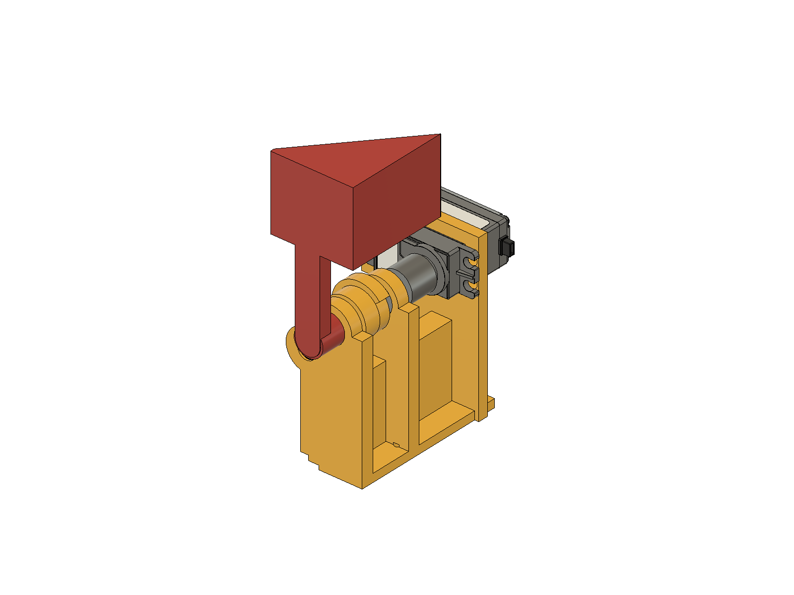
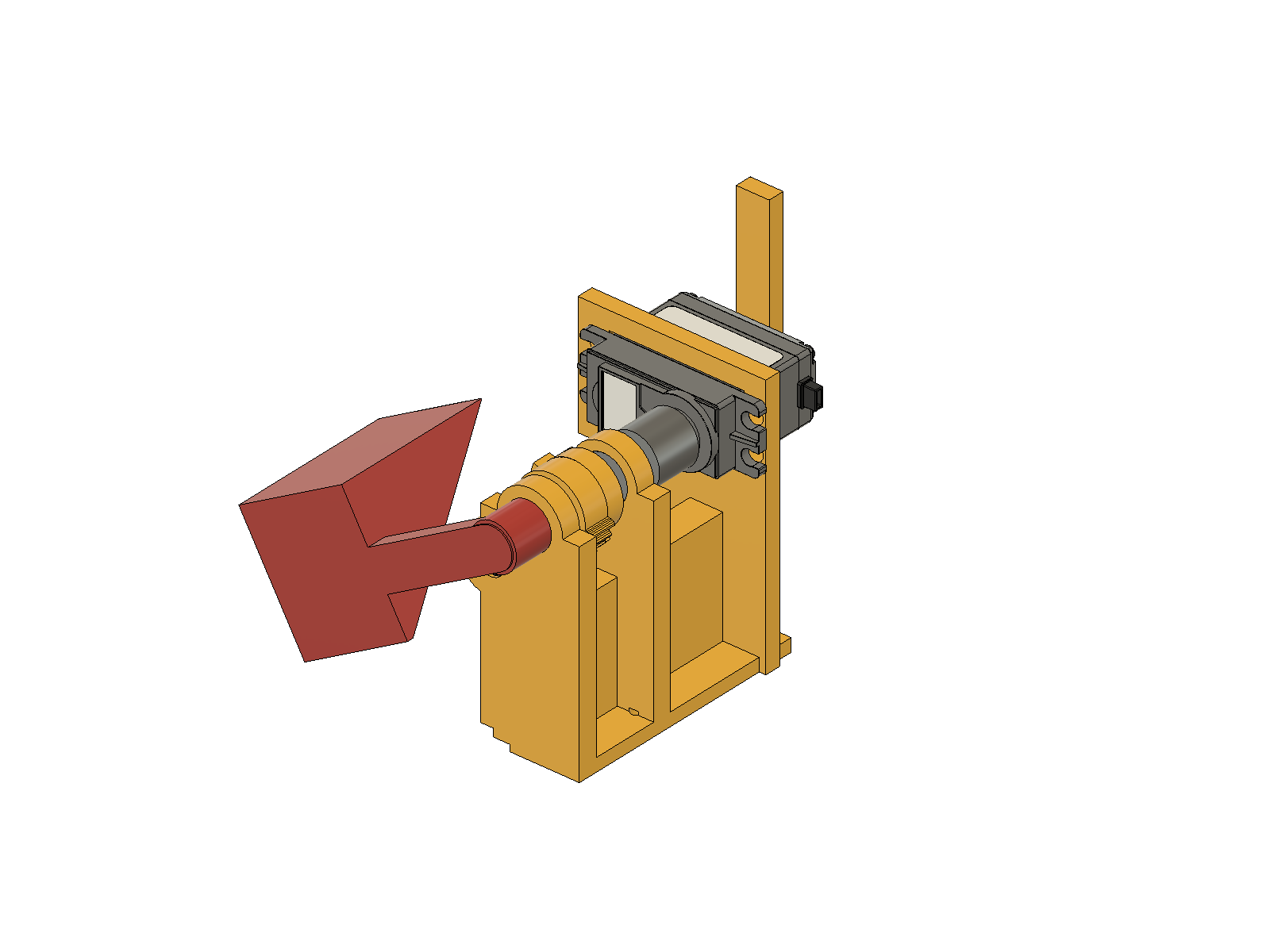
In the Fusion pictures the blade and the gate arm are red, the printed parts orange, the servo dark grey and the shafts grey.
How it works. ONE goBILDA Torque servo 2000-0025-0002 sits on the blade axis (x 106, z 40, shaft along y). It turns the 8 mm REX blade shaft, which carries the wedge blade (front end) and the 23-tooth blade gear. The blade gear drives the 14-tooth gate gear on the gate shaft (x 94, z 25.5), which carries the gate arm (rear end). The gears are cut so that the gate leads: it lifts a full 90 deg while the blade has moved only about 58 deg of its 120 deg stroke. Then a locking sector on the blade gear holds the gate open while the blade finishes its stroke. On the way back the gate closes as the blade parks. The blade is PARKED at "blade travel 0" (+90 deg in the CAD) and strokes to "blade travel 120" (-30 deg in the CAD): CAD angle = 90 minus blade travel.
Parts
| Part | Qty | File or part number |
|---|---|---|
| Torque servo 2000-0025-0002 | 1 | buy ($36.99 from the 2026-11-08 BoM) |
| One-servo frame, printed (plate 24) | 1 | V7_one-servo_frame_print_2026-11-15.stl |
| Blade gear 23T with locking sector, printed | 1 | V7_blade_gear_23T_lock_print_2026-11-15.stl (+ STEP) |
| Gate gear 14T with locking disc and stop tab, printed | 1 | V7_gate_gear_14T_lock_tab_print_2026-11-15.stl (+ STEP) |
| Wedge blade with REX hub, printed | 1 | V7_wedge_blade_REX_hub_print_2026-11-15.stl |
| Gate arm with REX hub, printed | 1 | V7_gate_arm_REX_hub_print_2026-11-15.stl |
| Clamping coupler 4001-0025-4008 (25T spline to 8 mm REX) | 1 | buy |
| 8 mm REX shaft 56 mm, 2106-4008-0560 (blade shaft, y -50..6), confirm SKU | 1 | buy |
| 8 mm REX shaft 96 mm, 2106-4008-0960 (gate shaft, y -37.5..58.5), confirm SKU | 1 | buy |
| Flanged bearing 1611-0514-4008 | 4 | buy (two 2-packs; a fifth goes in the windmill) |
| M4 screws, servo ears | 4 | goBILDA M4 packs; length not set |
| M3 screws, frame foot | 3 | owned stock; length not set |
| E-clips | 2 | with the REX shafts |
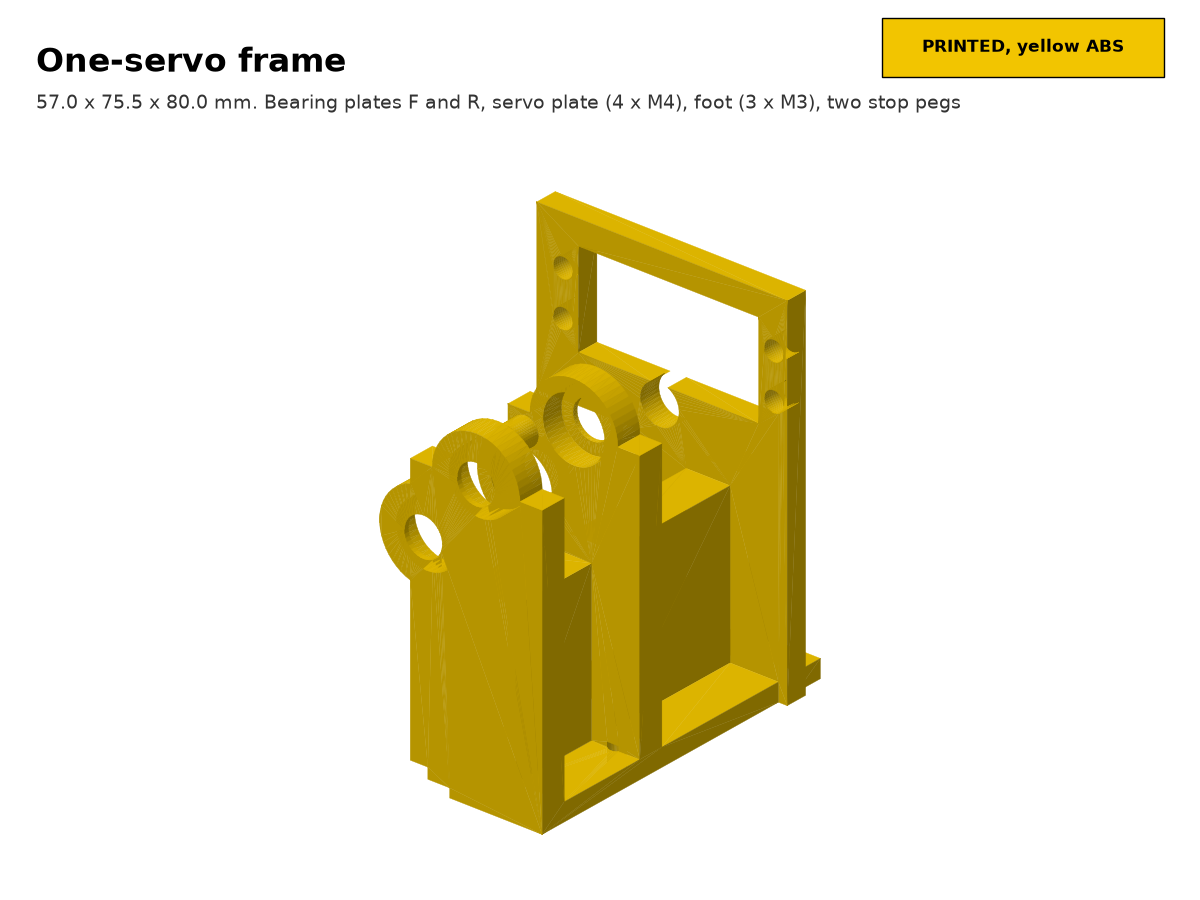
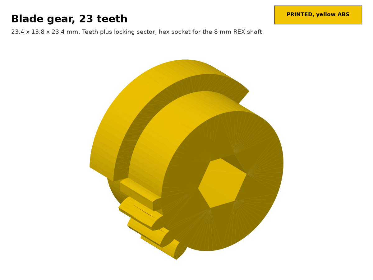
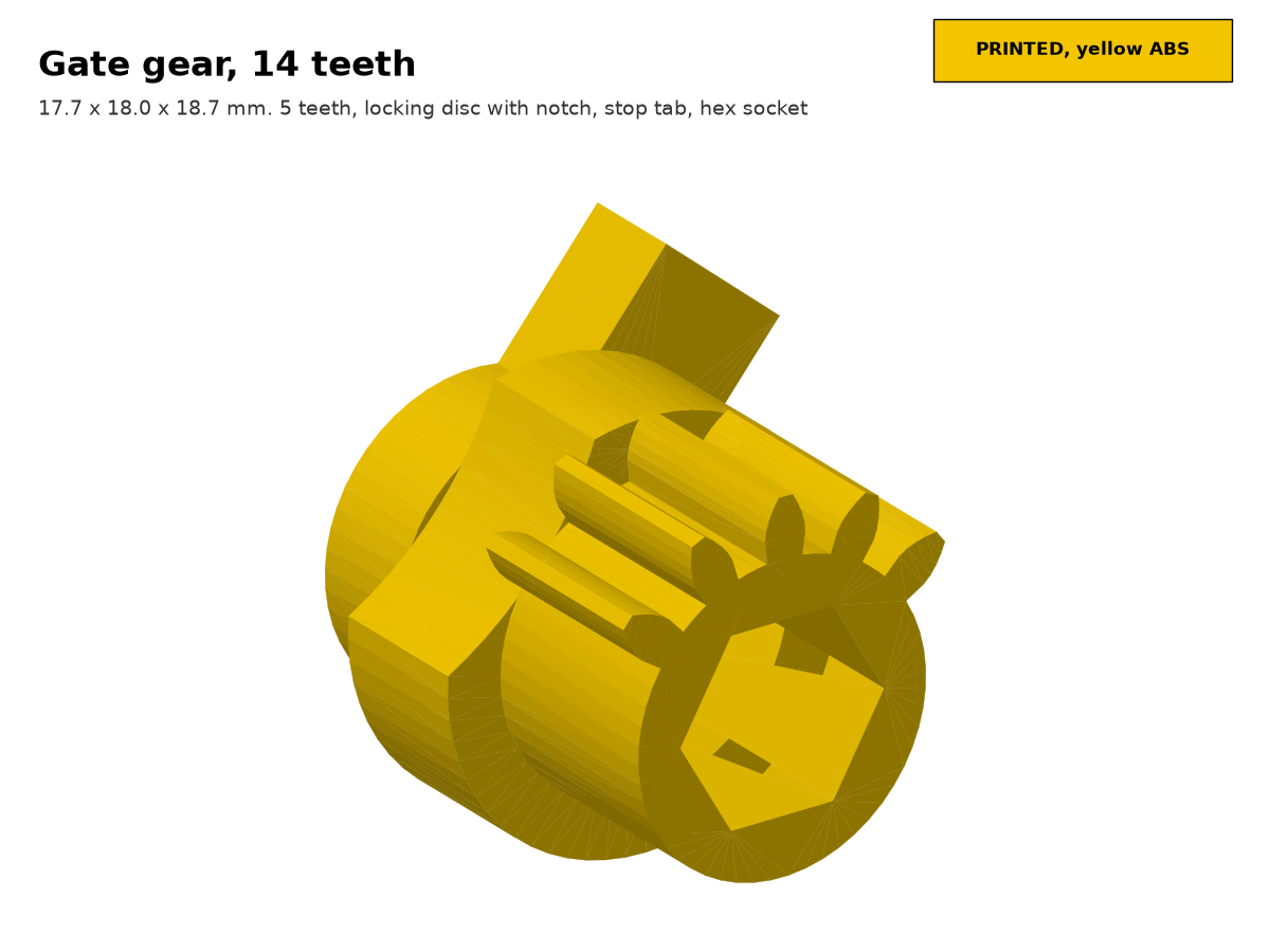
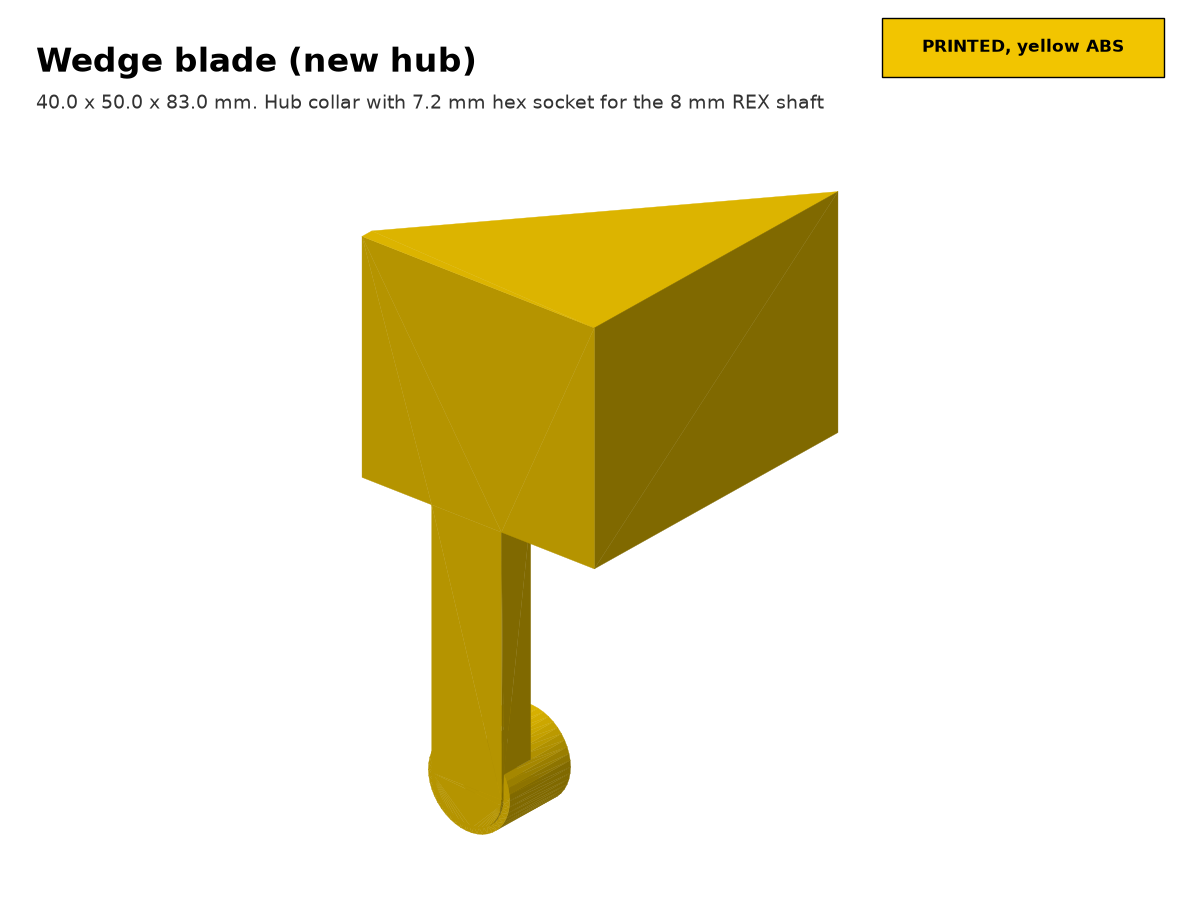
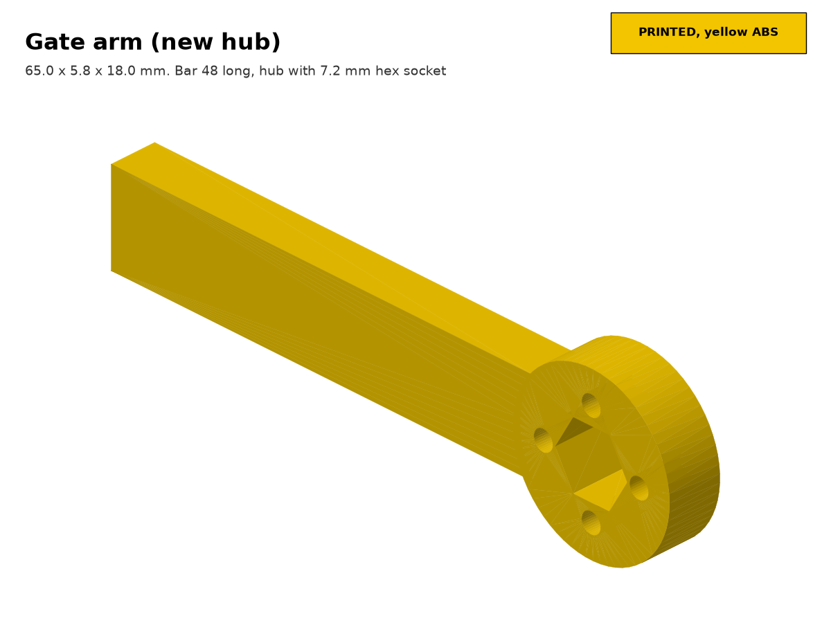
Key numbers. Gear pair: 23 teeth on 14 teeth, ratio 1.643, module 1.0174, pressure angle 20 deg, centre distance 18.82 mm. The gate axis is 0.5 mm lower than before (z 25.5) so that the 8 mm gate shaft clears the servo body. The servo body is x 76..116, y 7.5..51.8, z 30..50, turned so that the connector (x 116..121) faces the side plate at x 124; the ear flange is x 68.8..123.2. The frame (57 x 75.5 x 80 mm) has an F and an R bearing plate, a web, a foot, a servo plate behind the ear flange, a slit bush for the gate shaft and the two stop pegs. The wedge blade has a hub collar (r 7) with a 7.2 mm hex socket at y -50..-40; the gate arm has a 7.2 mm hex socket through its hub.
Do the gear fit check first (B9, steps 1 to 5), before you build anything on the robot.
- Gear fit check done and passed (B9).
- Press one 1611-0514-4008 bearing into each of the four shaft holes of the frame (blade shaft and gate shaft, in the F plate and in the R plate).
- Fit the frame on the floor's foot slab (it is cut to sit on it) and fix it with the 3 x M3 through the foot (which holes: Check against CAD C19).
- Servo into the frame: ear flange against the servo plate, 4 x M4 at x 72 and 120, z 35 and 45. The spline tip is at y 7.5, pointing to the front. The connector faces +x and ends 0.8 mm from the side plate: route the servo cable before the side plate goes on.
- Clamping coupler on the spline tip (14 mm long, r 8). Slide the 56 mm blade shaft (y -50..6) through the bearings and into the coupler. Do not tighten the coupler yet.
- Blade gear on the blade shaft (hex socket, y -32..-18.2 for the gear and locking layers). Wedge blade on the front end of the same shaft (y -50..-40).
- Slide the 96 mm gate shaft (y -37.5..58.5) through its bearings. Gate gear on it (stop tab toward the pegs). Gate arm on the rear end (arm bar y 54..59).
- Set the phase. Turn the blade to PARKED (blade travel 0). The gate must be CLOSED to within 1 deg (the tab resting on or just off the closed peg). The gears are cut so that they mesh in one position only: turn the gate gear until it meshes and the tab sits at the closed peg. Then tighten the coupler on the spline and on the blade shaft.
- E-clip each shaft at the plate faces. End float must be zero (shims and set screws are not drawn: Check against CAD C19).
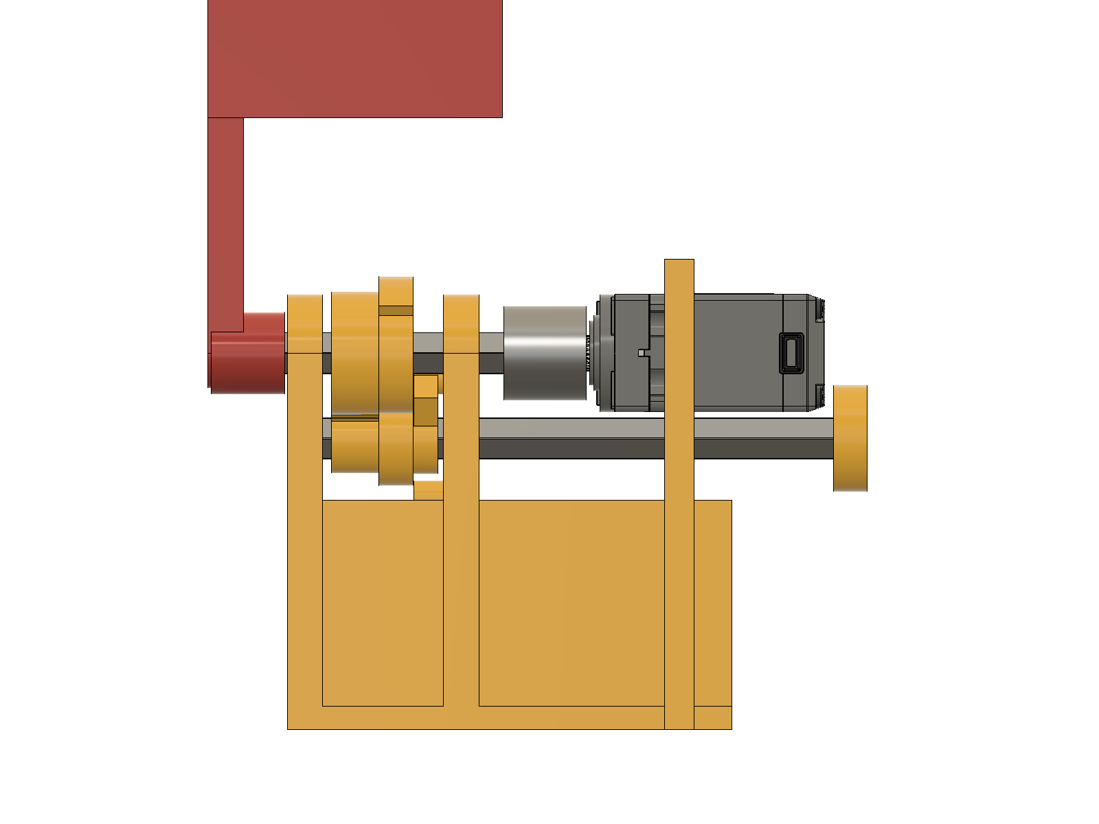
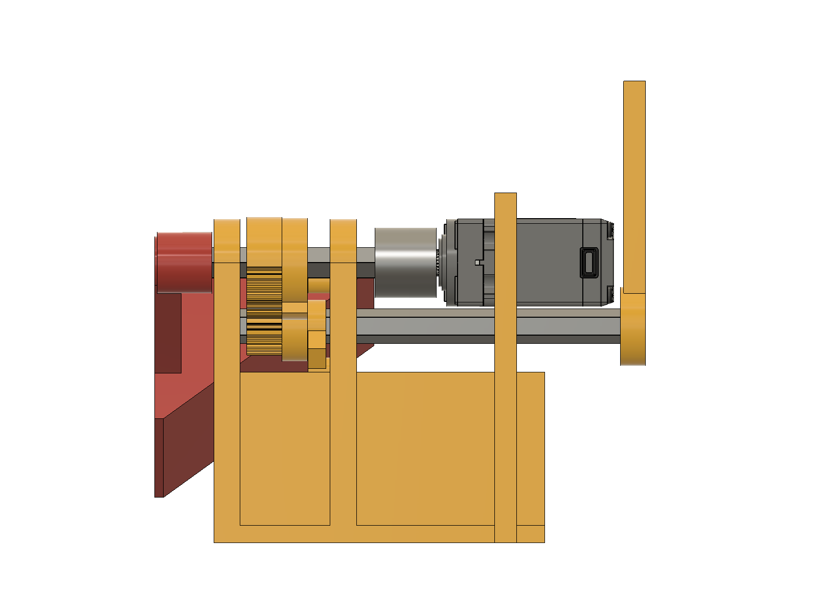
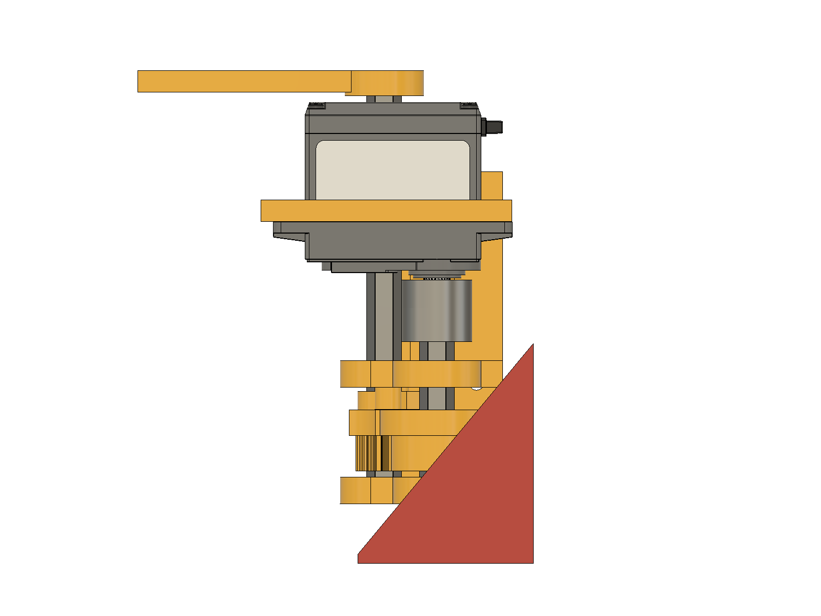
Clearances in the CAD (all checked over the whole stroke, 37 poses, 0 clashes): wedge hub face to frame 0.5 mm; wedge to servo at least 23.7 mm; gate gear to the kerb top 0.5 mm; gate shaft to servo body 0.5 mm; gate arm hub to servo end 1.4 mm; servo to side plate 0.8 mm. These are small. Do not add washers or thicker prints without checking.
Check: Sweep the blade by hand from parked to blade travel 120 (CAD +90 to -30): it must not touch the kerb, the floor, the rails, the vanes (parked), the ramp or the servo. The gate arm rises to 90 deg and stays there; it does not touch the kerb, the Hogback (6.75 mm minimum at the small-ball carriage pose) or the ramp. Both shafts turn freely by hand with no end float.
B9. Gear fit check, hard stops, lock and torque
Gear fit check (do this on the bench with the plate 24 prints, before anything is fitted to the robot). The gears are printed in ABS only to check the fit. Print the gears first, mesh them on two 8 mm REX shafts, check the gate reaches about 88-90 deg at blade travel 57-60 deg and locks.
- Print the blade gear (23T) and the gate gear (14T). Check that both hex sockets take an 8 mm REX shaft (drawn 7.2 mm across the flats: write down the real fit).
- Put the two gears on two 8 mm REX shafts that are 18.82 mm apart (use the printed frame with its bearings, or two bearings in a bench block).
- Turn the blade gear forward and write down the gate angle at the blade travel values below. The CAD gives:
| Blade travel, forward (deg) | 0 | 30 | 55 | 57.5 | 60 | 90 | 120 |
|---|---|---|---|---|---|---|---|
| Gate angle (deg) | 0.0 | 48.5 | 86.5 | 88.5 | 90.0 | 90.0 | 90.0 |
- Pass: the gate reaches about 88-90 deg at blade travel 57-60 deg and then stays at 90 deg and locks up to blade travel 120.
- Turn the blade gear back. The CAD gives: blade travel 120 to 55: gate 90.0; blade travel 50: gate 83.0; blade travel 30: gate 50.0; blade travel 0: gate 1.0. So the gate is closed to within 1 deg when the blade parks (backlash).
- Lock test: with the blade at travel 80 to 120, push the gate arm by hand. It must not move more than about +-1.25 deg (the lock window of the CAD).
If the angle at travel 57-60 is more than 1 deg off, report the measured values to the lead. Do not file the teeth by guess: the tip radius of tooth 3 sets the final gate angle (0.1 mm of radius is 1.1 deg), and the lock window is only +-1.25 deg. The locking sector has no lead-in chamfer yet (a 2 mm chamfer at the leading corner is to be added in the CAD): if the sector catches the disc, report it.
Hard stops. The stop tab on the gate gear (y -18..-14) runs between two pegs on the frame.
- Closed stop at a gate angle of about -0.4 deg. The closed gate holds a large ball against the ball load.
- Open stop at about +90.8 deg. The gate locks at 90.0 deg, so the open peg is only a back-up 0.8 deg later.
- The tab is clear of both pegs from -0.4 to +90.8 deg.
Closed peg takes the tab with the gate shut. Open peg is not touched in normal running.
Load path. A ball pushing on the CLOSED arm (up to 1.6 N m) goes arm, hex socket, tab, closed peg: peg force about 150 N, peg d 6 mm stress about 22 MPa, tab root about 28 MPa. ABS yields at about 40 MPa, so this is marginal: if the tab or a peg cracks, print them in PETG-CF or nylon, or thicken them. The radial load of the lock goes into the blade-shaft bearings, not into the servo.
Torque. The Torque servo stalls at 2.12 N m at 6 V. While the gate rises (blade travel 0 to 58), lifting the gate takes about 0.18 N m at the gate, which is 0.30 N m at the blade shaft (0.33 with 90 % mesh efficiency). That leaves about 1.8 N m (85 %) for the blade push; after the lock (travel above 58) the blade has the full 2.12 N m.
If the gate jams. A jammed gate pushes the whole stall torque (2.12 N m) through one tooth: about 180 N, about 80 MPa on an 8 mm ABS tooth. Use nylon or PA-CF for both gears, or limit the servo current while the gate moves. The CAD agent recommends nylon or PA-CF gears if the gate jams: the ABS print is for the fit check.
Not yet measured: the strength of the lock against ball loads on the OPEN arm (estimate 0.7-1 N m, limited by the strength of the plastic). Test it (C2 test 2.5) and write the value down.
B10. Battery cradle (was: battery tray)
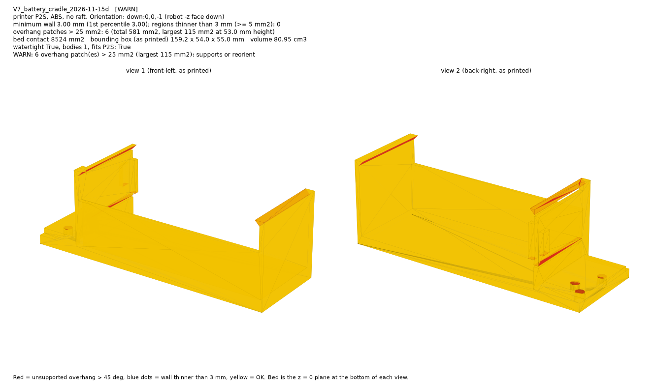
B10 update 2026-11-15 (late): battery cradle at the rear left (spot A)
Mark's decision, 2026-11-15: spot A, rear left, lying flat, slides out the back. The battery (kit battery 3100-0012-0020, 124 x 48 x 43 mm along x / y / z) is centred about (-86, 165, 52). The old tray, its 6 M3 holes and the two strap slots are gone from the underplate (DXF 15b/16c has 28 holes), so the tray of plate 21 is superseded.
- Part:
V7_battery_cradle_2026-11-15d.stl, 159.2 x 54.0 x 55.0 mm, 80.95 cm3, K1C, yellow ABS, plate 36, printed as in CAD (z down). Gate WARN: 6 overhang patches of 581 mm2 on the rail lips and latch, outside faces, removable support there only. - 2026-11-17: the servo power injector sits behind the rear channel under the rear end of the cradle, with only a 2.75 mm gap along y 192..196 (B12). The battery slides out the back: keep the injector harness (y 212..250) out of its path.
- Fixing and latch: not stated in the sources (Check against CAD C20). Do not invent one. The old strap 2909-0102-0250 is probably no longer used because its slots are gone: confirm.
Steps: 1. Print plate 36. 2. Find the cradle's fixing and latch in the Fusion model (C20) and fit it. 3. Slide the battery in from the back and out again twice: it must slide freely and the latch must hold. Check: Battery clears the ramp and the SPM. The battery cannot slide out under drive loads (hold test 4.2).
Earlier text of this chapter (2026-11-15), kept for history
Where it disagrees with the 2026-11-16 text above, the 2026-11-16 text wins. Parts marked superseded are not used.
Superseded 2026-11-15 (late): the tray below.
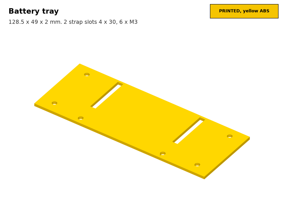
Parts: printed tray (128.5 x 49 x 2 mm, at x 0..128.5, y 122.5..171.5, z -24..-22), 6 x M3x8 + nuts, battery strap 2909-0102-0250 through the two 4 x 30 mm slots, kit battery 3100-0012-0020. The battery sits at x 2..127, y 124..170 lying across.
- Tray on the underplate: 6 x M3x8 and nuts.
- Battery on the tray, strap through both slots, tight.
Check (test plan 1.4): Battery top clears the ramp (CAD: 5.0 mm). Strap fits the slots and holds: not confirmed that a 20 mm strap fits (Check against CAD C16).
B11. Sensors
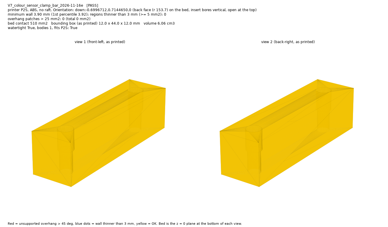
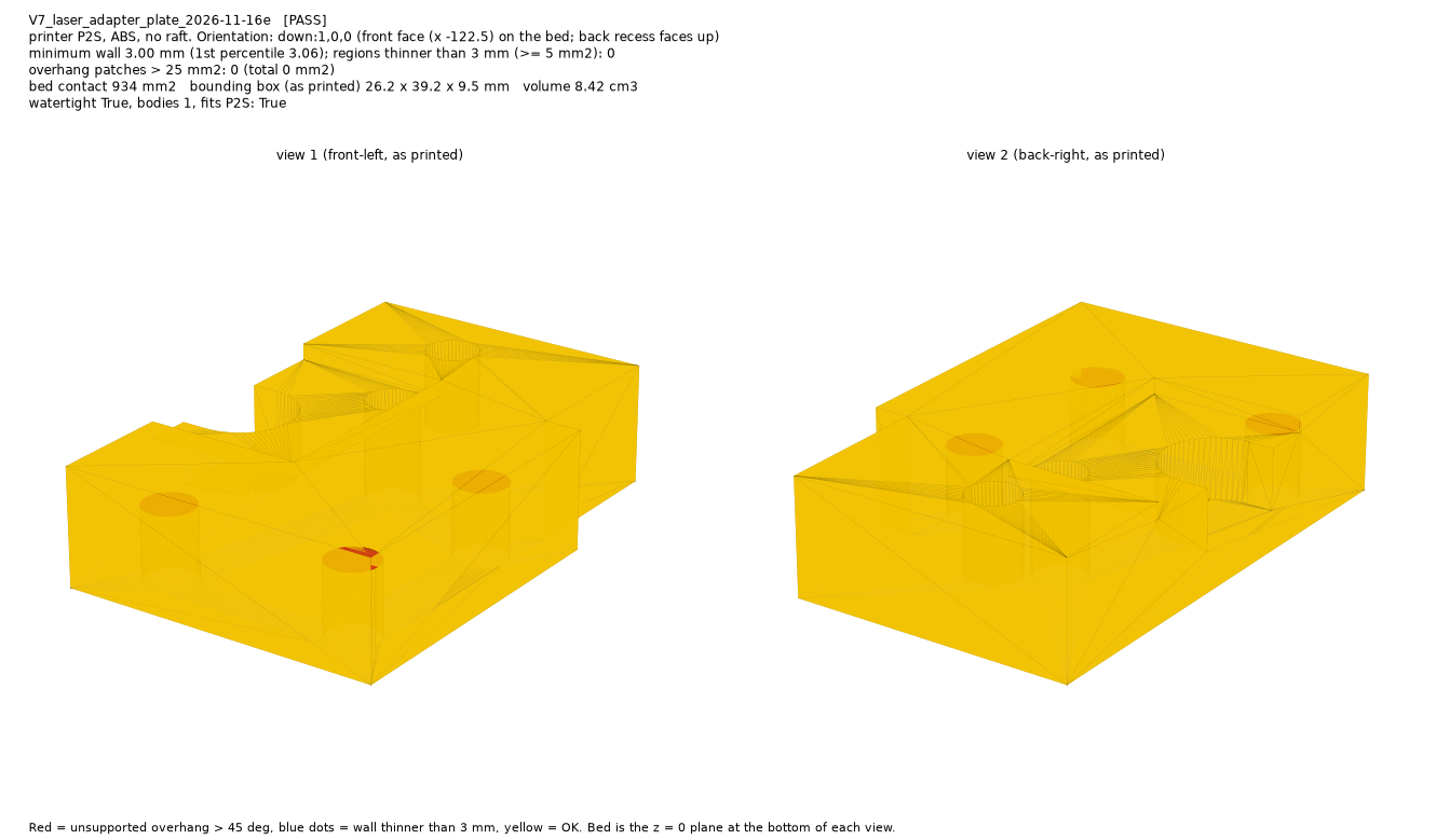
B11 update 2026-11-17: cameras (C920 landscape at 30 deg, Limelight later, C270 housekeeping)
Roles. The C920 is fixed, about 30 deg up, landscape, and looks at the HIVE AprilTags. The Limelight 3A is ordered and will replace the C920. The C270 is the housekeeping camera (balls inside the robot) and stays. No camera is on a servo: there is no free servo.
C920 (plate 11c, K1C, yellow ABS, est 1 h 57 min, 49.5 g; not printed)
- New case v9 (replaces the two C920 halves of plate 11 and the M3 block of plate 10b): pocket 80.6 x 22.6 mm, outline 106 x 30, lid 3 mm with an O11.0 lens window, a cable slot with a pinch ridge, 4 M4 heat-set inserts (5.6 x 6) for 4 x 2800-0004-0008 lid screws, and wings for 4 x 2800-0003-0008 (M3x8) into 4 M3 inserts in the adapter. Parts: base, lid, adapter (STLs
V7_c920_case_base,..._lid,..._adapter_2026-11-17c1c.stl; the c1 and c1b files are superseded). - Landscape: the case and the camera are turned 90 deg about the lens axis. Lens at (-134.0, 139.5, 329.6), elevation 30 deg, axis (0, 0.866, 0.5). The 106 mm case runs along x and stops at the mount L plate face (x -80.7).
- Adapter (wedge on the 4 mm mount L tab): 4 x 2800-0004-0008 (M4x8) into M4 threads you tap in the tab at x -112 / -98, y 113.7 / 152.2, z 292..296. The tab has no holes today. (Old positions y 122.6 / 170.6 are void.)
- View (225 rays, 2 m): the HIVE tag elevations 31 to 48 deg are clear. The FLOWER at fire (azimuth +-26.4 deg) is clear. Only 3 rays at the top edge hit the D3 Q2 hairpin. The top margin to the HIVE tags is 3.5 deg.
- Not verified: the board, lens and connector sizes come from the Fusion V4 camera model, not from the real camera. Measure the board and the barrel with calipers before printing. The board has about 1.5 mm of up-and-down play (a foam pad is not modelled). The adapter overhangs the tab edge by 10.7 mm and is bolted through 4 flange holes only.
- Limelight 3A: 72.1 x 48.1 x 16.8 mm, 93 g, USB-C to the Control Hub blue port. It needs a new adapter (its body is larger than the C920 seat). goBILDA showed it sold out on 2026-11-17.
C270 (plates 10c and 10d, K1C, yellow ABS; not printed)
- The old 11-08 case, hood and the 6061 strap are not used. The camera stays at its high-left pose (lens at (-120, -70, 280), 62 deg down toward the ball centroid).
- Plate 10c (est 2 h 03 min, 46.5 g): shell (pocket 70.6 x 30.6 x 25.6, window 62 x 26, no hood), back plate (4 x 2800-0003-0008, a raised pad with 2 M4 inserts) and an adapter wedge (2 x 2800-0004-0020 along the case axis, counterbored). Plate 10d (est 1 h 03 min, 25 g): the arm. Arm foot 2 x 2800-0004-0012 into the adapter inserts. The wall pad bolts to the outer face of the mount L wall with 4 x 2800-0004-0008 into threads you tap in the 4 mm wall at y 28 / 46, z 346.5 / 354.5.
- Cable exit: unknown, so the shell has a strain-relief slot in both long walls.
- Not verified: the camera size and lens position are the Fusion model's. The arm is a 131 mm cantilever (hand numbers only, no vibration test). The mount L outer face was assumed free for y 20..54, z 322..360.
B11 update 2026-11-16: colour clamp bar, hall bracket and laser plate (plate 36, K1C, yellow ABS)
| Part | File | Size mm | Fixings | |
|---|---|---|---|---|
| Colour sensor clamp bar | V7_colour_sensor_clamp_bar_2026-11-16e.stl |
44 x 12 x 12, 6.06 cm3 | standing on its back face (down:-0.6997,0.7145,0), bores vertical, bed 510 mm2, no support; gate PASS (min wall 3.9) | 2 x M3 heat-set inserts (4.2 x 5.7, from the front face, s = +-16, z 30) and 2 x 2800-0003-0016 (M3x16) through the sensor ear and the shelf-plate holes; 3.4 mm through holes to the back face for the screw tip |
| Hall sensor bracket (REV-31-1462 seat) | V7_hall_sensor_bracket_2026-11-15d.stl |
31.5 x 27.0 x 67.1, 13.65 cm3 | down:-1,0,0; gate PASS (min wall 3.01) | not in the sources (Check against CAD C14) |
| Laser adapter plate | V7_laser_adapter_plate_2026-11-16e.stl |
26.2 x 39.2 x 9.5, 8.42 cm3 | front face (x -122.5) on the bed (down:1,0,0), bed 934 mm2, no support; gate PASS (min wall 3.0) | 5 x M3 heat-set inserts (3 in the front, 2 in the back; fit the 3 front inserts from the bed face and the 2 back ones from the top); 3 x 2800-0003-0014 (M3x14) on the module side, 2 x 2800-0003-0008 (M3x8) on the web side |
- Why the earlier clamp bar and laser plate were bad: the 15d clamp bar had its bores cut in the wrong place (it had no holes), and the 15d laser plate had 0 mm slivers and a flange pocket 1.2 mm from a bore. Both are fixed in the 16e files (the 15d files are superseded). Open on the bar: its lower edge touches the chassis channel 1120-0015-0384:2 (gap 0.0 mm).
- Laser (decision 2026-11-15): the goBILDA laser distance sensor now sits on goBILDA aluminium (a 1121-0005-0144 shelf on the left carriage bar, Check against CAD C21) with the printed adapter plate, and the beam is horizontal across the intake throat in front of the windmill (+x at y -157, z 11) to detect a ball coming in. It no longer looks down from hood H. The old M16 bracket and its 4 x M4x18 + 2 x M4x14 are superseded.
- Sensor part number in CAD: the REV colour sensor is REV-31-1537 (the brief said 1557); check the box.
- Not tested: insert pull-out, print fit of the 0.3 mm flange and shaft clearances, motion sweep of the intake shaft against the laser plate.
Steps: 1. Print plate 36 (bar, hall bracket, laser plate, cradle). 2. Heat-set the bar's 2 inserts and the plate's 5 inserts. 3. Clamp the colour sensor with the bar (2 x M3x16). 4. Fit the laser plate and module (3 x M3x14 module, 2 x M3x8 web); aim the beam across the throat. 5. Fit the hall bracket over the r 40 magnet position once its seat is confirmed (C14).
Earlier text of this chapter (2026-11-15), kept for history
Where it disagrees with the 2026-11-16 text above, the 2026-11-16 text wins. Parts marked superseded are not used.
Superseded 2026-11-16: item 3 (laser on hood H, M16 bracket) below. Items 1, 2 and 4 stand, with the new clamp bar and hall bracket above.
- Colour sensor (REV Color Sensor V3), windmill rear-left pocket. Shelf and back plate (50.9 x 50.5 x 21.5) clamp the sensor with 2 x M3x16 through the plate and the case into the 2.5 mm pilots in the rail wall. Lens at z 30 looking at the axis, through a 16 x 14 hole in the rail (NW side). No wiggle. Lens looks through the hole (test plan 1.5).
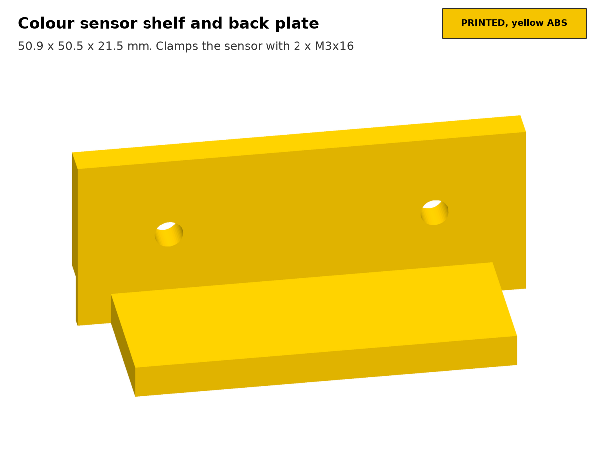
- Magnetic limit switch REV-31-1462 over the r 40 magnet at the rest spot, with the M10 bracket (trimmed annulus r 34..46). The bracket screws need a seat on the windmill servo block (not drawn: Check against CAD C14). The magnet passes 3.9 mm under the switch at each stop.
- Laser distance sensor 3124-0001-0001 on the printed M16 bracket (4 x M4x18 and 2 x M4x14 with nyloc) on hood H; looks down at the intake. Pot set to about 98 mm.
- Cameras (superseded 2026-11-17, see the update above). C270 (ball camera, high on the left, lens at (-120, -70, 280)) and C920 (AprilTag, rear-up). Both brackets bolt to the FLOWER shelf mount L, which is part of the later FLOWER work (see B14). Today: assemble the cases and brackets and test the USB cameras on the bench; mark them "waiting for mount L". Do not invent a temporary fixing.
FUSION VIEW F07 (placeholder): Sensor positions: colour sensor in the rail hole, hall switch, laser on the hood, cameras, from above and from the left
B12. Electronics, signs and switch (hub mounts)
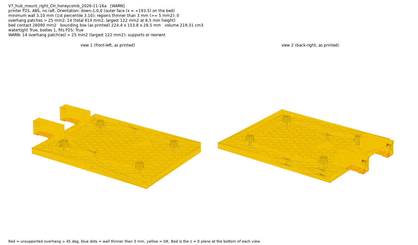
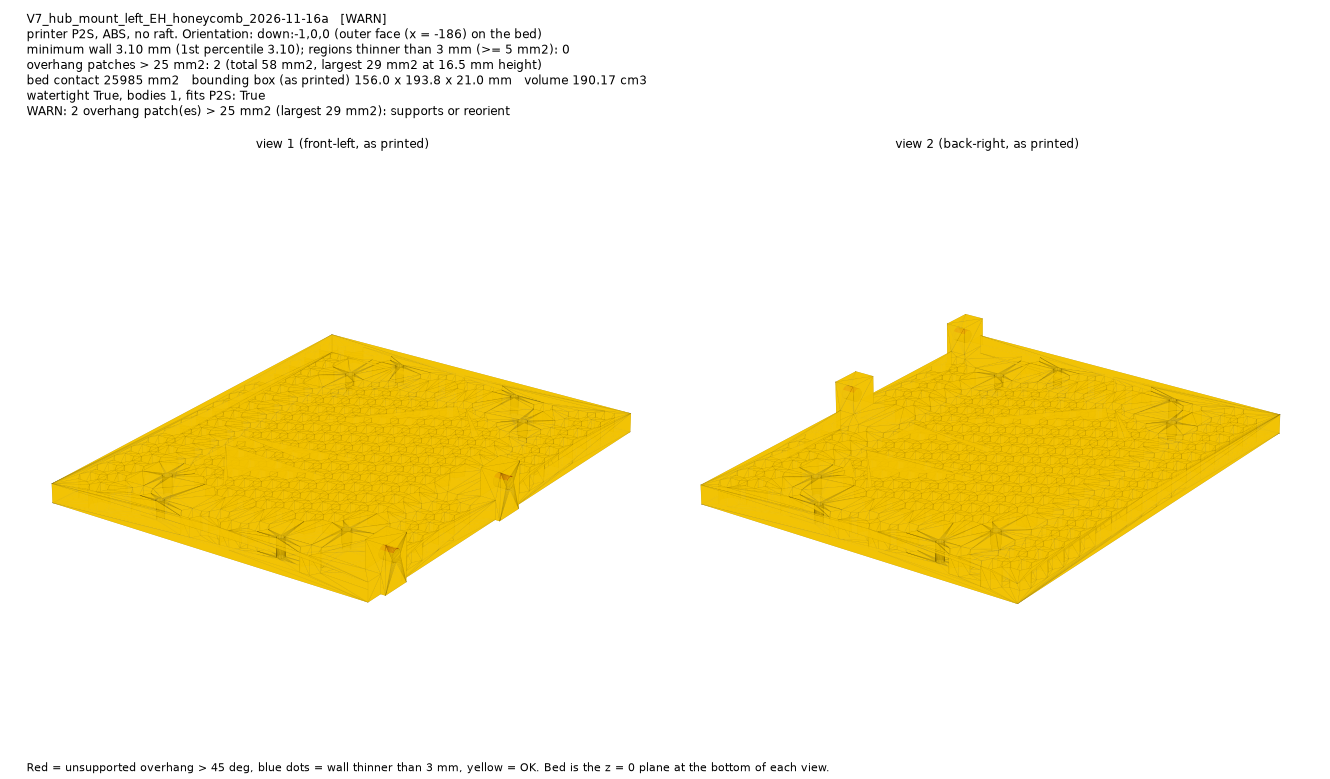
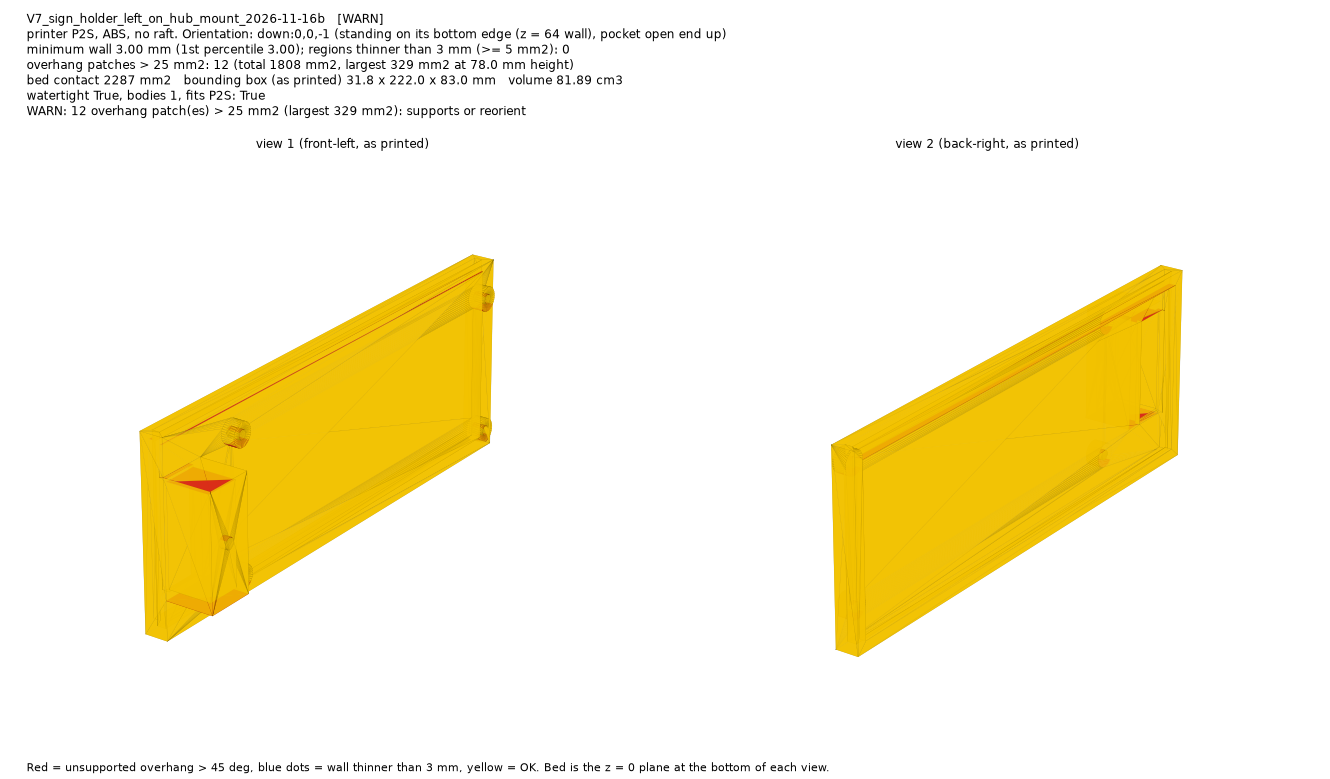
B12 update 2026-11-17: servo power injector (replaces the REV Servo Power Module)
Mark dropped the REV Servo Power Module (REV-11-1144) for the goBILDA 6V Servo Power Injector 3125-0001-0001 (one unit; enclosed, 6 channels, 8-15 V in). The REV unit is owned but not used. The old SPM spot (x 104..125, y 128..167) has no free 32 x 32 hole pattern.
- Part: body 40 x 42.5 x 19 mm, 62 g. 4 mounting holes on a 32 x 32 mm square. Its pack has 4 x M4x20 screws and 4 M4 nyloc nuts.
- Position: OUTSIDE the rear channel 1121-0010-0264 web (web face y 192), centre x -36, z 0, body y 192..211.4, x -56.5..-15.7, z +-21.3. The input pocket faces -x toward the battery. The two header blocks are at the top and bottom ends; the plugs point rearward (+y).
- Screws: 4 x 2800-0004-0020 (M4x20) through web holes at x -52 and -20, z -16 and +16, with the 4 nyloc nuts inside the channel. The nuts are not modelled (checked as 4.1 mm cylinders, 0 clashes). No printed parts.
- Gaps (CAD): battery cradle floor 2.75 mm (only along y 192..196), underplate 4.3 mm, battery body 11 mm, ramp 55 mm. Plugs and wires need about 25 mm behind the injector. Rear end y 211 plus plugs is well inside the 349.6 mm rear limit. The power lead (XT30) is short.
- Not verified: 12 connectors (6 in, 6 out) in a 42 mm height: check on the real part that the plugs and the 3 mm cradle lip clear. The STEP has no plug models.
Steps: 1. Fit the injector to the rear channel web: 4 x 2800-0004-0020 and 4 nyloc nuts. 2. Check it clears the cradle floor (2.75 mm) and that the battery still slides out the back. 3. Wire it (B13).
B12 update 2026-11-16: raised hubs on honeycomb hub mounts, new number frames
The Expansion Hub plate v4, the K2 electronics bay (old EH plate, spacers, M3x12 screws, washers), the V6 Control Hub mount and the 4 aluminium sign brackets are removed / superseded. Each hub now sits on one printed honeycomb mount (cells 8.0 mm across the flats, every wall 3.1 mm, 25.4 mm surround on all four sides, plate 8.5 mm thick).
| Part | File | Size mm | |
|---|---|---|---|
| Hub mount left, Expansion Hub (x -177.5..-186) | V7_hub_mount_left_EH_honeycomb_2026-11-16a.stl |
156.0 x 193.8 x 21.0, 190 cm3 | P2S, ABS; outer face (x -186) on the bed (down:-1,0,0); gate WARN: 2 patches of 29 mm2 |
| Hub mount right, Control Hub (x 185..193.5) | V7_hub_mount_right_CH_honeycomb_2026-11-16a.stl |
224.4 x 153.8 x 28.5, 219 cm3 | P2S, ABS; outer face (x +193.5) on the bed (down:1,0,0); gate WARN: 14 patches of 914 mm2 under the 2 risers (support needed there, 7.5-8.5 mm tall) |
| Sign holder left (with the sign colour sensor chamber) | V7_sign_holder_left_on_hub_mount_2026-11-16b.stl |
31.8 x 222.0 x 83.0, 81.9 cm3 | P2S, ABS; stands on its z = 64 bottom wall (down:0,0,-1), bed 2,287 mm2, brim; removable support under the lip window top bar and the left chamber underside |
| Sign holder right | V7_sign_holder_right_on_hub_mount_2026-11-16b.stl |
16.2 x 222.0 x 83.0, 73.2 cm3 | same |
The work order says the hub mounts are PETG; the team default is ABS. Confirm before printing.
- Hubs raised (smallest raise that gives a full 25.4 mm surround and at least 2 mm to everything): Expansion Hub +23.6 mm (z 51.6..154.6); Control Hub +52.0 mm (z 80.0..223.0). The left is limited by the chassis channel, the right by the rear-right drive wheel and the pod stop block R.
- Fixings per hub: 4 x M3 heat-set inserts (4.2 x 5.7, opening toward the hub) and 4 x 2800-0003-0016 (M3x16) from the hub front through the hub's own holes (with the 0.5 mm nylon washer under each hub screw as before). Each mount has 2 feet on the chassis top flange (M4 insert 5.6 x 6, 1 x 2800-0004-0008 (M4x8) from below through an 8 mm flange hole at x +-172; left y -80 and 0, right y -96 and -32): 4 x M4 inserts and 4 x M4x8 in all. The right mount has two risers (x 165..186) to reach the flange.
- Number frames (sign holders): bolted on the outer face of the mounts, each with 4 bosses (D10.4) carrying M3 heat-set inserts, fixed from the hub side with 4 x 2800-0003-0014 (M3x14) through the mount plate (8 in all). Holders moved outboard 2.5 mm (left) and 10.0 mm (right). Wall thickness raised to 3.1 mm or more everywhere (min wall 3.00 mm on the gate, the pocket bottom). The left sign colour sensor (REV-31-1537) and the power switch REV-31-1387 moved with the left holder (the switch also 1.6 mm toward -y).
- Inserts for B12: 16 x M3 (4.2 x 5.7) and 4 x M4 (5.6 x 6).
- Not swept: arm and shot motion (the mounts are at x +-165..208, y -145..99, outside the windmill, the shot corridor and the intake sweep). The 2 mm clearance envelope is clean.
Steps
- Print the two mounts and the two holders (check cards and Mark's OK first). Add supports only where listed.
- Heat-set 4 M3 inserts per hub mount, 4 M3 inserts in each holder's bosses, and the 4 M4 inserts in the feet.
- Fit the mounts to the chassis top flange with 4 x 2800-0004-0008 from below.
- Fit the Expansion Hub (left) and Control Hub (right) with 4 x 2800-0003-0016 each and the nylon washers.
- Fit the sign holders to the mounts from the hub side with 8 x 2800-0003-0014. Fit the left sign sensor and the switch.
- Check no hub screw touches the frame and the hubs clear the drive wheel (2 mm).
Earlier text of this chapter (2026-11-15), kept for history
Where it disagrees with the 2026-11-16 text above, the 2026-11-16 text wins. Parts marked superseded are not used.
Superseded 2026-11-16: items 1, 2 and 4 below (Expansion Hub plate, Control Hub mount "file missing", old holders and brackets). Items 3, 5 and 6 stand.
Carried over from V5 with the positions of the V7 model. The V5 book chapter P6 has the fixing detail; where it disagrees with this book, this book wins.
- Expansion Hub on its mount plate on the left (plate x -181..-178, hub on edge, x -177..-148, y -70..73, z 28..131).
- Control Hub standing at +x behind the sign (x 148..177, y -119..-16, z 28..171) on the PETG Control Hub mount (x 178..185). The mount file is missing (Check against CAD C9).
- (Superseded 2026-11-17: the goBILDA servo power injector, see above.) Servo Power Module (RR-SRV-PU-BD-A) at the rear on the battery, stood on edge (x 104..125, y 128..167, z 38..130). Its fixing is not drawn (Check against CAD C16).
- Signs: left holder (with the alliance colour sensor, REV colour sensor V3) and right holder (x -198..198, y -122..98, z 24..147 together). Signs not yet made.
- Power switch REV-31-1387 on top of the left sign above the sign colour sensor (z 147.5..179). The surround is hidden in V7: Check against CAD C17.
- Every hub screw has its 0.5 mm nylon washer and no hub screw touches the frame.
B13. Wiring
B13 update 2026-11-17: servo cable plan (read-only study, stages/servo_wiring_2026-11-17.md)
Routes are estimates (Manhattan paths x 1.15 for slack, plus a service loop at any moving joint). Nothing was tested on the robot or in Fusion. The old SPM wiring step is replaced: servos are powered through the goBILDA injector (6 V), not the REV SPM.
Facts used. Axon MAX and MINI leads are 300 mm (3-pos TJC8). The goBILDA servos have 300 mm leads. Extension lengths that exist: 150, 300, 450, 600, 900, 1200 mm. There is no 200 mm. The injector has 6 signal inputs and 6 outputs, and comes with 6 x 200 mm cables (MH-FC to MH-FC).
Port map (a proposal; no ports are documented for V7)
| Where | Port | Servo |
|---|---|---|
| Expansion Hub (left, nearest the injector) | S0 | FLOWER lift L |
| S1 | FLOWER lift R | |
| S2 | spout roll | |
| S3 | blade and gate | |
| S4 | wedge | |
| S5 | nest flap | |
| Control Hub (right) | S0 | windmill (continuous) |
| S1 | flywheel carriage |
All six Expansion Hub ports go to the six injector inputs. The Axons feed back on analog ports if used (not decided).
Extension per servo (servo to injector output; windmill and carriage go to the hub)
| Servo | Routed length | Lead | Extension to use |
|---|---|---|---|
| Blade and gate (Axon MAX) | 435 mm | 300 | 150 mm |
| Wedge (Axon MAX) | 781 mm | 300 | 600 mm (450 is 30 short) |
| FLOWER lift L (Axon MAX) | 607 mm | 300 | 450 mm (300 is only 7 mm short: the one close call) |
| FLOWER lift R (Axon MAX) | 662 mm | 300 | 450 mm |
| Spout roll (Axon MINI, rides the swing arms) | 796 mm + 263 mm loop | 300 | 900 mm, one cable; the loop sits at the lift axle |
| Nest flap (Axon MINI) | 267 mm | 300 | none (33 mm to spare); keep a 150 spare |
| Windmill (goBILDA 25-2) | about 300 mm | 300 | 150 mm for margin |
| Carriage (goBILDA 25-3) | 150 mm | 300 | none |
| Hub to injector, 6 signal cables | 401 mm each | 200 (supplied) | 300 mm in series with each supplied cable |
To order (spares included; matches the final BoM): 150 mm x3, 300 mm x7, 450 mm x3, 600 mm x2, 900 mm x2 (12 are needed). If the Axon feedback leads also take extensions, add 2 x 150 mm and 1 x 600 mm.
Routing rules
- Every Axon cable ends at the injector outputs on the rear face. They arrive along the outside of the rear channel (y about 215, z about 17) from the left end (x -134) or the right end (x +134). Nothing can cross the channel (the injector sits on its web, the cradle over its top). Web holes pass a wire but not a plug.
- Left servos (nest, wedge, lift L, roll) go down the left upright outside face, x about -112. Right servos (blade and gate, lift R) go down the right wall, x about 125 to 135.
- No cable may drop through x -91..+123 at y 100..245 above z 213. That is the D3 sweep. Lift L, lift R and the roll servo go outboard to x -112 or +132 first.
- Dress the wires up and round the rear channel end. There is a row of zip-tie holes in the channel flange at y 184.
Not verified (check on the first fit)
- The hub servo-port edge is not documented. Assumed to face the rear and inboard. Each hub run can be wrong by about 50 mm (300 mm still covers it).
- The Axon feedback (a 4th wire): lead length and connector are not on the vendor page.
- Chain order and genders on the bench: hub port, extension, supplied 200 mm cable, injector input.
- Wedge servo: the plan assumes the boom is on the chassis side of the pod hinge (it is, B16). If a servo ever rides the pod, add a loop of about 105 + 50 mm.
- The routed path along the left upright is not checked for clashes. The battery slide-out and the harness at y 212..250: confirm the direction before you tie anything down.
Wiring note, 2026-11-16: the hubs moved up, so every hub cable is longer. The table below still holds.
Cable lengths are not modelled in the CAD, these are the extra lengths needed over the old hub positions:
| Cable group | Extra length needed |
|---|---|
| Control Hub (right, raised 52.0 mm): every cable | about +52 mm |
| Expansion Hub (left, raised 23.6 mm): every cable | about +24 mm |
| Left sign colour sensor and power switch (they moved outboard with the left holder) | about +2.5 mm |
Check the motor, encoder, servo, I2C and USB cables before you fit them: any cable that was just long enough now needs the next standard length (or an extension). Route them clear of the rear-right drive wheel and the pod stop block R.
Use the port map in the Appendix. Cable lengths are not in the CAD.
- Battery to switch to the hubs and to the servo power injector (it feeds the servos at 6 V; the SPM is gone, 2026-11-17).
- Four drive motors, flywheel motor, pod motor.
- Servos (8 with the FLOWER D3): windmill, carriage, the ONE blade-and-gate servo (Axon MAX), the FLOWER wedge servo (Axon MAX, left, B16), and the D3 servos: lift L and lift R (Axon MAX), spout roll and nest flap (Axon MINI) (B14). There are no corner-wheel servos any more (gear drive, B15). Cable plan above.
- I2C: Pinpoint, colour sensors; digital: hall switch, laser.
- Keep every cable clear of the blade stroke, the gate arm, the gears, the rotor and the pod swing. The blade-and-gate servo connector is 0.8 mm from the side plate: route its cable before that plate goes on.
B14. FLOWER D3 tube and lift (approved 2026-11-17; build on Sunday)
What it is. D3 is a short, wide, slick-walled tube over the rear of the robot. It catches the shot ball and drops it into the FLOWER. A passive nest flap with a concave notch sits under the FLOWER pipe cage. At fire, the spout is rolled 40 deg toward -x, which keeps the robot inside the 24 in length limit (R105.B) mechanically: the end of the helical cam slot is the hard stop. One pivot on the tower tops swings the tube 104 deg forward, driven by the two Axon MAX servos through a crank and a link. To stow, the tube needs a 90 deg roll plus a 70 mm telescope, both from the helical slot. The full design page is on the team site: /d3.html.
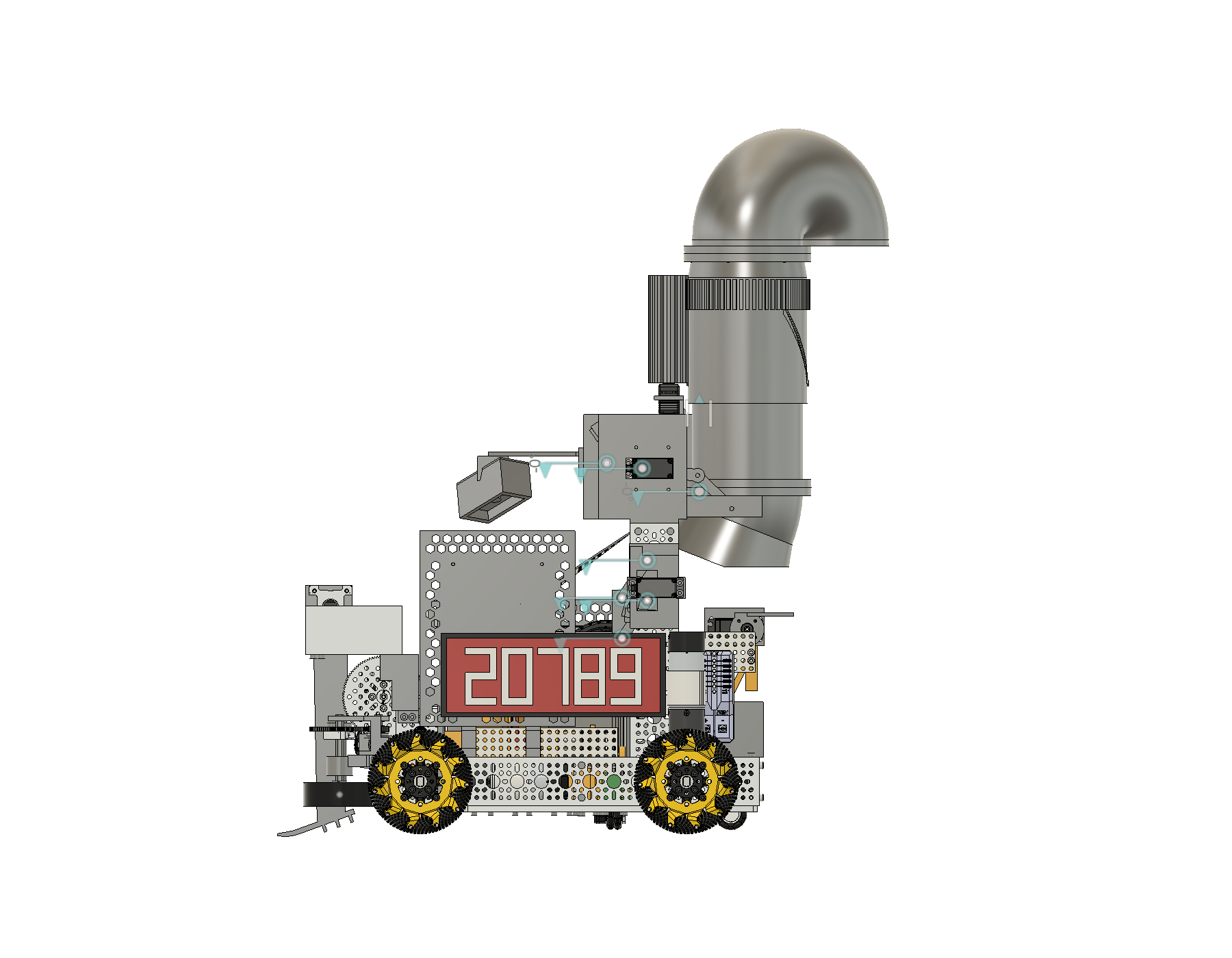
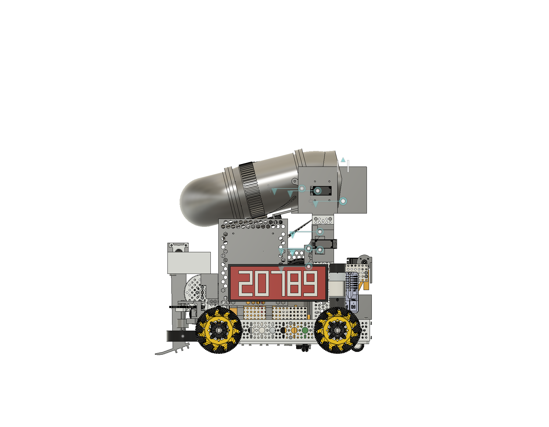
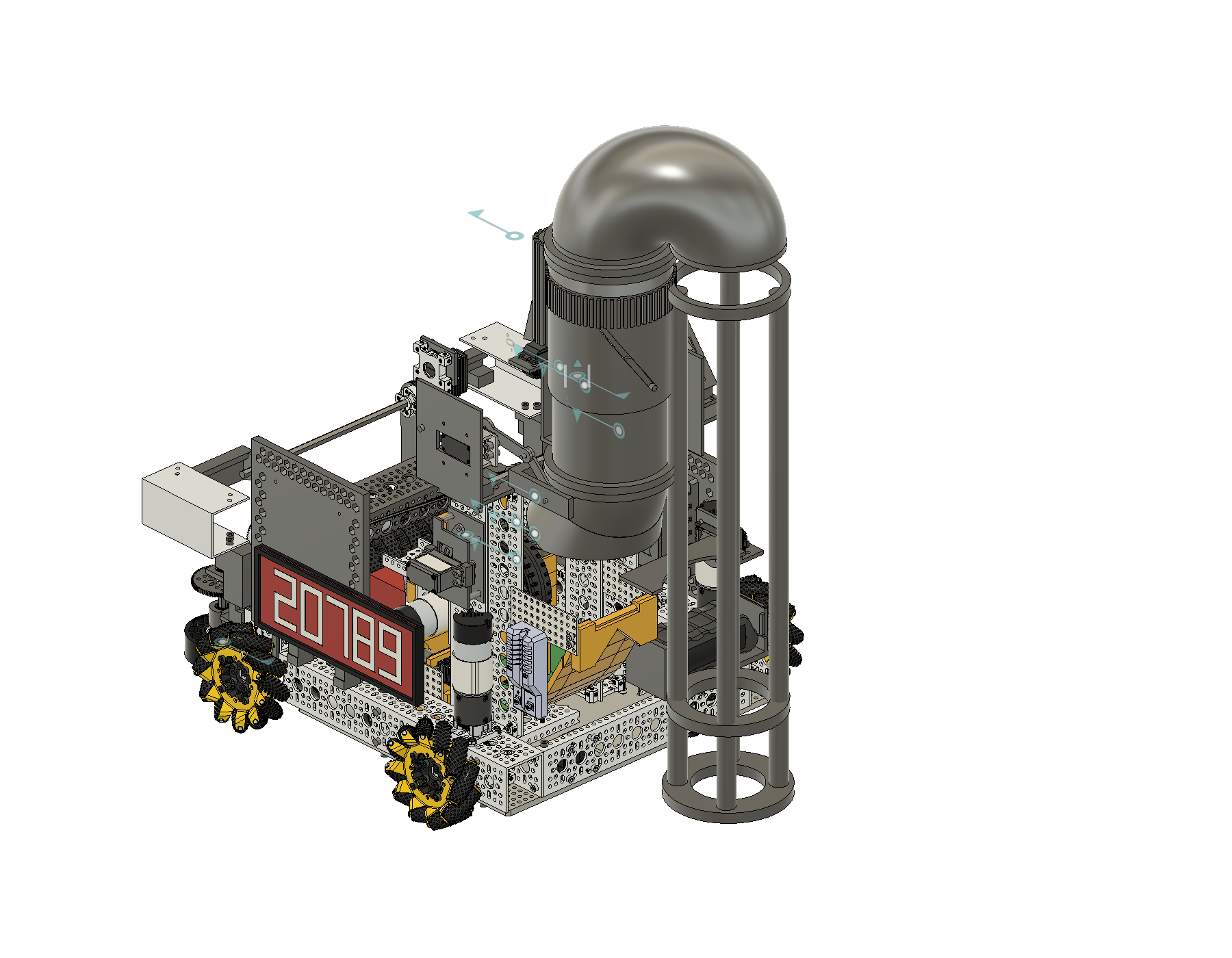
These renders are the first D3 pass. The D3b and D3c changes below altered the parts in detail, so small details differ.
Not final, under review (the guide keeps today's version):
- Q2 hairpin: redesign under review (a pointed-arch hairpin, plates 53a and 54a). Build the current D3c hairpin (plates 53 and 54) unless Mark says otherwise.
- Nest flap spring and latch: under study. It would remove the nest Axon MINI. Until that is decided, the nest keeps its servo. A link-driven flap (no servo) was checked and is not feasible: every link plane crosses the P1 funnel at fire.
Numbers (CAD, mm)
| Item | Value | Limit or note |
|---|---|---|
| Fire pose, rear / top | y 320.5 / z 647.8 | limits y 349.6 / z 684.6 |
| Length, wedge down, tube at fire | 320.5 + 285.8 = 606.3 | 609.6 (margin 3.3) |
| Stowed D3 | y -231.0..130.1, z 195.0..404.1, x -131..106 | cube top z 405.2: margin 1.1 at the P1 flange |
| Fire pose clearance, funnel to tower | 3.2 | tight |
| Lift four-bar (D3b) | crank 31.2, link 30.6, pin r 32.8; 111.6 deg of servo for 104 deg of tube | crank angle -51.5 deg = fire, -163.1 deg = stow |
| Lift torque | about 0.75 N m per side at the arm; about 1.4 N m at the servo | Axon MAX stall 3.33 N m at 6 V (2.4 x) |
| Sim of the 40 deg rolled hairpin | NECTAR 100/100, POLLEN 100/97; nest +-5 / 10 / 20 mm: 100 / 78 / 29 % | fire at 4.0 to 4.5 m/s, not 5 (worst POLLEN 70 % at 5 m/s); a 35 deg roll would be about 612 mm long, so 40 deg stays |
The sim numbers are CAD and offline checks. The tube is not printed or tested yet.
What D3b and D3c changed (so it can be printed and built)
- A real lift collision was fixed: the four-bar now sits in one flat arm plane (x -19.2..-13.2) outside the hub, crank and link planes.
- The axle is a fixed goBILDA 2106-4008-1920 (REX, 192 mm) in two printed hex clamps on the shelves. Each swing arm turns on one 1611-0514-4008 bearing. Two 2910-0920-4008 collars hold the axle in place sideways.
- The roll pinion sits on a goBILDA 4001-0025-4008 coupler and a 2106-4008-0560 stub. The pinion pocket now fits the real coupler (clamp ear and screw head) and has a screw access hole. Its hex bore is 7.30 mm across flats.
- Roll bracket: 2 x M3 into F2 heat-set inserts, a C-section column. Telescope clearance 0.4 mm per side. Flange screws are flipped so they can seat.
- Nest servo carrier: bolted to the left 1117 plate by the two existing ramp screws, lengthened from M4x10 to M4x14.
- D3c, no supports: Q1 prints upside down on its flange with a chamfered gear ring; P1 prints flange down; P2 flange down; the nest carrier, the wedge posts and others were re-oriented. The tube halves Q2 (plates 53, 54) are the exception: a bent tube has no orientation without supports, so they use tree supports under the outside only.
Parts
Printed (yellow ABS, final; plates in B0)
| Part | Plate |
|---|---|
| P1 funnel + bend, roll pinion 18T | 50 |
| P2 sleeve (fixed inner sleeve, OD 110, 2 cam pins) | 51 |
| Roll servo bracket (supports needed) | 51b |
| Q1 slide (over the sleeve, 60T ring, 2 helical slots, reducer to 104) | 52 |
| Q2 hairpin half A, half B (R55.5 + spout; weld with acetone) | 53, 54 |
| 2 swing arms, 2 cranks, 2 links, 2 axle clamps, pin-P spacer R | 55 |
| Nest flap + nest servo carrier | 56 |
Bought or owned
| Part | Qty | Note |
|---|---|---|
| Axon MAX MK2 2004-0025-0002 | 2 | lift L and R, owned |
| Axon MINI MK2 2004-0025-0001 | 1 owned (roll) + 1 to buy (nest) | |
| 2106-4008-1920 REX 192 mm | 1 | lift axle |
| 1611-0514-4008 flanged bearing | 2 | one per swing arm |
| 2910-0920-4008 clamping collar | 2 | axle, inboard of the arms |
| 1908-0025-0032 servo hub, 25T | 3 | 2 cranks + 1 nest flap; 2 may be in the bin from V5: look first (the site says 6 mm thick, the old guide said 8) |
| 4001-0025-4008 coupler + 2106-4008-0560 stub | 1 + 1 | roll pinion |
| Servo extensions | see B13 |
Screws and inserts for D3
- F1/F2: 6 x M3 heat-set (in F2, from below) + 6 x M3x10 (2800-0003-0010) from below.
- F3/F4: 5 x M3 heat-set (in F3, from the top) + 5 x M3x12 (2800-0003-0012) from above.
- F2 top: 4 x M3 heat-set (arm lugs, roll foot); arm lugs 2 x M3x8 and roll foot 2 x M3x8 (2800-0003-0008).
- Axon MINI ears (roll, nest): 8 x M3x10 + 8 M3 nuts (team stock).
- Cranks to the 1908 hubs: 8 x M4x8 (2800-0004-0008).
- Pins: pin Q left M4x10 button head + thin nut, right M4x12 + nut; pin P left M4x16 + nyloc, right M4x20 + nyloc + the printed spacer.
- Axle clamps: 4 x M4x12 (2800-0004-0012) into holes you drill and tap in the shelves. Nest carrier: 2 x M4x14 (team stock; or M4x16 + a washer).
- Flap to hub: 4 x M4x8 into the hub threads.
Build order (Sunday)
- Bench measurements first: the real FLOWER pipe cage, the Axon MINI ear pattern, the 1908 hub hole pattern (16 mm square assumed), the REX across-corners size. Fit a cam pin in a slot and the slide on the sleeve dry (0.4 mm per side; sand if tight).
- Shelves: remove camera screws #2 (x -44, y 99.3) and #4 (x 108, y 99.3) (their heads sit 0.6 mm into the axle line). Drill O3.3 and tap M4 for the axle clamps (x -55 / 125, y 77.5 / 112.5, 2 per clamp).
- Heat-set inserts: F2 (6 from below + 4 on top), F3 (5 on top).
- Tube: P1 + P2 (M3 from below); roll bracket on F2 with the roll Axon MINI (M3 on the ear notches); coupler + stub + pinion; slide Q1 over the sleeve (both pins in the slots); weld the Q2 halves with acetone; Q2 on F3 (M3 from above).
- Lift: bearings into the arm bosses; axle through the left clamp, left arm, collars, right arm, right clamp; bolt the arm lugs to F2; hubs and cranks on the Axon MAX (zero the servos first); links and pins.
- Hand-cycle 0 to 104 deg with the wedge DOWN, before any power. Check the link-to-P1 gap at stow (1.4 mm) and the right arm to the shelf corner (1.4 mm).
- Nest: carrier on the 1117 plate (M4x14 into the ramp inserts, replacing the 2 x M4x10), the Axon MINI, hub, flap.
- Drop tests: NECTAR and POLLEN with the spout rolled to 40 deg. If the ball does not leave cleanly, try 45 deg (rear 313.9 mm) before anything else.
Tight margins and open risks
- Clearances: link to P1 1.4 mm at stow (narrow the link to 6 mm if it rubs), right arm to the shelf corner 1.4 mm, axle bottom flat 0.6 mm over the shelf, arm hub 0.65 mm over the left tower top, pinion to the slide 0.68 mm during the retract.
- The arm-to-tube joint is one clamped M3 lug per side (watch for creep). Q2 is held to Q1 by 5 screws, all in half B (half A only through the acetone weld).
- The wedge must be DOWN while the tube passes 82 to 103 deg of swing, or the stowed wedge toe touches it (D3 first pass: set this in software). The Q2 hairpin and the tube must clear the wedge in the hand-cycle.
- The real FLOWER pipe cage (assumed 4 pipes OD 19 at R 47.5) and gear teeth play are not measured. R503 allows 8 servos: D3 uses all 8, no spare.
- The static model used for the clash run was made before the C920 case and the W5 wedge were added. It found only the intended contacts.
FUSION VIEW F08 (placeholder): The D3 tube and lift in place on the robot, side view and top view
Earlier text of this chapter (2026-11-16), kept for history
Superseded 2026-11-17 by D3 (above). The V5 tube, cranks, links, saddle and the "keep this space free" numbers below were for the older design. D3 reaches z 647.8 at fire.
Not built today. Not designed here. Already made and waiting: tube P, arch Q (split A and B), pinion, links, cranks (partly). Waiting on the redesign: tube P/arch Q pose, cranks and links, saddle, shelf mounts L and R, lift ear brackets, the Axon servos (2 MAX, 1 MINI) and the camera fixing to mount L. A recommended replacement (open half-pipe hood, 0 servos) is in flower_designs_2026-11-15/.
Keep this space free: x -118..150, y 17..283, z 211 and above (the tube in the model reaches z 549, the arch z 656). Leave the upright tops clear. Do not put anything on the left upright top or the area for shelf mount L (x about -80, z 256..364). Keep the robot inside the starting size: 18 in cube, 5.1 / 5.2 / 8.2 mm of margin (width / length / height).
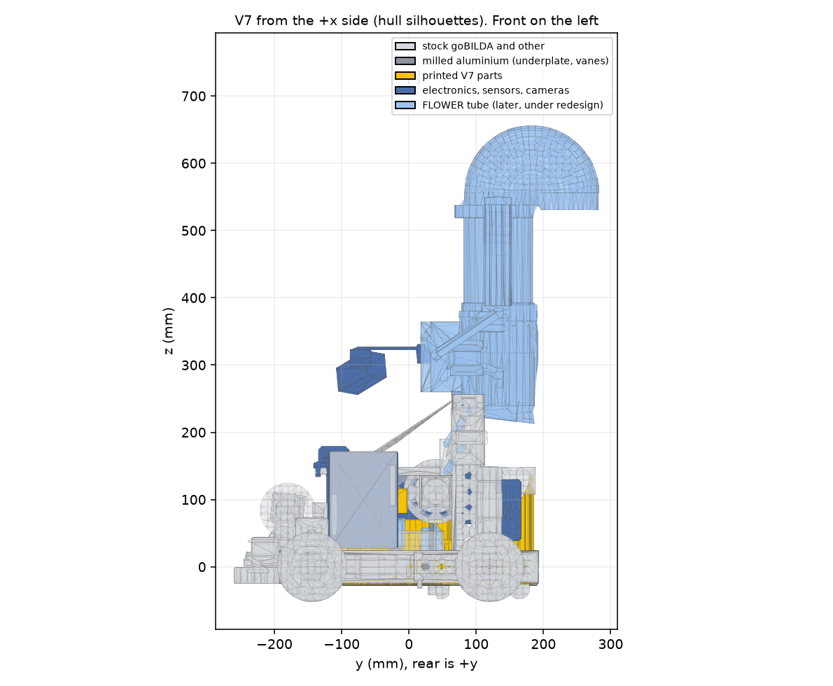
B15. Corner-wheel gear drive (parts 16k and 16m; decided 2026-11-16)
What it is. The two 72 mm corner wheels at the front are driven by gears from the intake pod axle, so they need no servo. The pod floats (lifts for a large ball), and the gear carriers are mounted on the pod, so the mesh moves with it. Mark: keep the wheels, gear-drive them at the tested speed, mount them on the pod. The wheels could not move back (rail flanges), so the length stays 456.0 mm (limit 457.2).
Ratio. Intake roller 585 rpm -> corner wheel 103.2 rpm (the tested speed was about 100 rpm). Train per side: printed bevel pinion 9T : bevel gear 17T (module 1.6, 30 deg pressure angle), then goBILDA 24T : 72T spur gears (the 72T sits on the corner wheel hub).
B15 update 2026-11-17: yellow REX bevels, real goBILDA gears, shafts
- Bevel pair re-bored to the REX hex shaft. The old pair had a D-bar bore. The goBILDA REX shaft is a hexagon, 7.0 mm across flats (8.0 across corners). The bevels now have a 7.30 mm hex bore (0.15 mm per side of clearance) with 0.4 mm lead-in chamfers. A hexagon fits at 6 angles, so the mesh phase can always be set at assembly.
- Printed: plate 39r, yellow ABS, 2 pinions 9T + 2 gears 17T, done (37 min, 8 g, K1C). These are the final bevels. The bevels on plate 39 (D bore) are not used. The carriers on plate 39 (grey) are unchanged.
- Clash fixes (S2), already in the plate 39r files: the 17T gear is turned 7 tooth pitches (148.235 deg) so its hex bore clears the 24T pinion and the bearing on the same shaft; the mesh has 0.30 mm of backlash taken off the 17T teeth (rotary play about +-0.25 deg). Shim the gear, do not squeeze it: moving the gear 0.2 mm toward the pinion makes a 0.57 mm3 overlap. Known and accepted: the pinion hex wall is only 1.20 mm and the gear 1.97 mm (the pre-print gate shows FAIL for this thin wall). ABS bores shrink: if a bore is tight on the real shaft, open it by about 0.05 mm.
- goBILDA gears are real vendor shapes now: 24T steel pinion 2322-4008-0024 (MOD 0.8, 7.0 mm wide, not 5) and 72T hub-mount gear 2312-0414-0072 (acetal, 4 mm; SKU inferred, verify). Centre distance 38.54 mm gives 0.126 mm backlash and no interference. Tooth phase: as imported, the teeth meet tooth-on-tooth. Turn the wheel half a 72T tooth pitch (2.5 deg) before you clamp the hub. The printed copies on plate 40 are for fit checks only.
- 72T bolts: the gear holes (4 x O4.4 on r 11.66) are 0.35 mm off the Sonic hub taps (r 11.31). A real M4 shank can bind by 0.14 mm. Start the 4 x 2800-0004-0008 loose; open the gear holes to 4.6 mm if they bind. Heads sit 2 mm under the carrier top plate.
- Shafts are REX hex in the CAD: roller shaft 2106-4008-2880, 2 x vertical shaft 2106-4008-0400, 2 x wheel axle 2106-4008-0720. Bearings 1611-0514-4008, hubs 1309-0016-4008 (4 Sonic hubs in all). The M3 grub screw for each bevel pinion is team stock (goBILDA has no M3 set screw).
- Wheel model fixed: the shared corner-wheel part had a 6 mm slab missing in the CAD. It was replaced with the vendor wheel 3613-0014-0072. Nothing on the robot changes.
- Pod rest stops, ratio and length: unchanged. Roller 585 rpm to wheel 103.2 rpm. Robot length 456.0 mm.
- Not verified: the printed hex on a real shaft, the tooth mesh and backlash on the real parts, nuts behind the pod flange (0.4 to 0.6 mm of room), pod float with the carriers on it.
Parts (2026-11-16 list; the bevel and gear rows are superseded by the update above)
| Part | Count | File or SKU | Status |
|---|---|---|---|
| Corner gear carrier LEFT 16m | 1 | V7_corner_gear_carrier_left_2026-11-16m.stl |
plate 39, printed (grey) |
| Corner gear carrier RIGHT 16m | 1 | V7_corner_gear_carrier_right_2026-11-16m.stl |
plate 39, printed (grey) |
| Bevel pinion 9T m1.6 PA30 | 2 (one per side) | V7_corner_bevel_pinion_9T_m1.6_PA30_2026-11-17s4.stl (REX hex bore) |
printed, plate 39r, yellow |
| Bevel gear 17T m1.6 PA30 | 2 (one per side) | V7_corner_bevel_gear_17T_m1.6_PA30_2026-11-17s4.stl (REX hex bore) |
printed, plate 39r, yellow |
| goBILDA 24T steel pinion 2322-4008-0024 | 2 | SKU OK in the BoM | buy |
| goBILDA 72T hub-mount gear 2312-0414-0072 (on the Sonic hub, 4 x M4) | 2 | SKU inferred: verify | buy |
| M4 heat-set inserts, 5.6 OD x 5 long | 6 + spares | verify source | buy |
| 2800-0004-0016 (M4x16) | 4 (2 per carrier, outer feet) | verify SKU | buy |
| 2800-0004-0008 (M4x8) | 2 (1 per carrier, middle screw into the in-channel plug) | verify SKU (already flagged) | |
| M3 grub screws in the printed pinions | 2 | not modelled | stock |
| M4 nuts behind the pod flange | check | not modelled | open check |
Obsolete, do not print or use: the 16k carriers (..._carrier_left/right_2026-11-16k.stl) and the 6 x 2800-0004-0010 foot screws with nuts inside the pod. The 16k bearing-seat 2 mm offset error is fixed in 16m.
What the 16m carrier changes. The carrier screws are reversed: the screw heads are inside the pod (on the pod web inner face at x 104 / -112) and the threads go into M4 heat-set inserts (5.6 OD x 5 long) pressed into the carrier bosses (x 116 / -124) and the in-channel plug. Walls are 3 mm minimum. Print on plate 39 (K1C, grey ABS, 5 walls, 20 %). No sim was run for the gears.
Build steps
- Test mesh first. The yellow bevels (plate 39r) are printed. Check the mesh and the backlash by hand before you fit anything else.
- Press the 4 + 2 M4 inserts into each carrier (heat-set, gently; check the carrier walls).
- Fit the carrier to the pod: 2 x 2800-0004-0016 (outer feet) from inside the pod web into the inserts, and 1 x 2800-0004-0008 (middle) into the plug insert. Check that the nuts, if any are used behind the pod flange, fit: there are only 0.4-0.6 mm of room (open check).
- Fit the bevel gear and the 24T gear on the corner shaft in the carrier, the 72T gear on the corner wheel hub (4 x M4), the bevel pinion on the pod axle with its M3 grub screw.
- Turn the pod roller by hand: both corner wheels must turn inward, with no binding through the pod's float.
- Restore the pod rest-stop bars (B2, item 4).
Check (bench, first day): Gear mesh and backlash by hand. With the intake running the corner wheels turn inward at about 103 rpm. Drive at 10 POLLEN and 10 NECTAR about 150 mm off the centre line: they should be pulled in (the sim: 30/30 with the wheels on, 23-25/30 off). Drive at a NECTAR so the pod lifts: the mesh must still run and the wheels still help. Nuts behind the pod flange fit.
B16. FLOWER wedge (v5 on the fixed chassis; updated 2026-11-17)
What it is. A drop-down ramp-wedge on the front. It lowers onto the tiles and lets a small ball roll up the ramp into the intake roller, to pull balls out of a FLOWER. Since late 11-16 it is NOT on the pod. It hangs from two fixed posts and two goBILDA U-channel booms, so the pod can float under it. On 11-17 it was split into three printed parts: the ramp body and two arms, screwed together (Mark's idea: print the arms flat on their own, then screw them on).
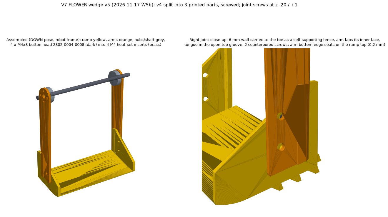
Numbers. Ramp 195.2 mm wide (centre x -4), 5 mm plate, 20 deg, 1.8 mm toe edge, R40 underside. The ball lane between the arms is 185.2 mm. Deployed, the toe is on the floor at z -54.4 and y -285.8 (25.8 mm ahead of the front-most robot point; outside the cube only while deployed). Stowed: x -228..228, y -258..-146, z 58..352. Robot length stays 456.0 mm. Stowed wedge to the stowed D3 tube: 4.4 mm. The rotating wedge clears the pod by 6.4 to 9.5 mm over the pod float (0 to 40 deg). Spare servo travel past contact is +1.0 deg.
Parts
| Part | Count | File or SKU | Status |
|---|---|---|---|
| Wedge ramp body (v5) | 1 | V7_FLOWER_wedge_195_v5_ramp_2026-11-17w5.stl |
plate 42t (P2S, yellow), printing, no supports |
| Wedge arm left, right (flat on the inner face) | 2 | V7_wedge_v5_arm_left/right_2026-11-17w5.stl |
plate 42s (arms only), printing or done (no finish note) |
| Wedge posts left, right (tab on the hinge block) | 2 | plate 44 (old holes), ..._post_left/right_2026-11-17w6.stl (new holes) |
44 printed, wrong holes; 44b to print |
| Crossing arms left, right | 2 | plate 44 (old holes), ..._crossing_arm_left/right_2026-11-17w6.stl (new holes) |
44 printed, wrong holes; 44b to print |
| goBILDA 1120-0003-0096 U-channel boom, 96 mm | 2 | one per side | buy |
| Axon MAX MK2 2004-0025-0002 | 1 | left side (late 11-16) | buy |
| ServoBlock 3217-0001-2501 | 1 | freed corner-wheel part, check on the bench | owned |
| 1309-0016-4008 Sonic hub | 2 | one per arm, inside the arms | |
| 1611-0514-4008 bearing | 1 | right boss (the left shaft end is carried by the ServoBlock output) | |
| REX shaft 2106-4008-2400 (240 mm) | 1 | x -117.4..122.6 | |
| 2802-0004-0008 (M4x8 button head) | 4 | arm to ramp wall, 2 per side | buy (W5) |
| M4 heat-set inserts 5.6 x 5.0 | 4 in the arms + 8 in the posts and crossing arms | not a goBILDA part | buy |
| 2800-0004-0010 (M4x10) | 12 | 8 arm to hub + 4 ServoBlock frame | |
| 2800-0004-0016 (M4x16) + M4 nyloc nuts | 4 + 4 | post tabs to the hinge block walls | SKU not checked |
| 2800-0004-0008 (M4x8) | 8 + 4 | 8 boom screws (post 4, crossing arm 4); 4 servo to ServoBlock, with 4 washers 2801-0004-0008 |
The v5 joint (per side)
- Each ramp end has an outboard fence wall (6.0 mm thick, x 93.6..99.6 and -107.6..-101.6) from the toe to the rear edge. It is a fence so the ramp prints toe-down with no supports at all (the W5b change). Its top edge is a 42 deg line: about 22 mm above the floor at the toe, rising to z 24 toward the rear.
- The arm lies against the wall's inner face over about 60 x 30 mm. A tongue (6.0 x 2.0 mm) on the arm fits an open-top groove in the wall. The ramp slides on along z until the arm edges seat on the ramp. Tongue gives y and rotation, the seat gives z, the screws give x.
- 2 screws per side, 21 mm apart, at z -20.0 and +1.0, from the wall outside: 2802-0004-0008 (button head, counterbore 8.0 x 2.4) into an M4 heat-set insert 5.6 x 5.0 in the arm. The tip stops 0.6 mm short of the arm's lane face. A socket-head 2800-0004-0008 would stand 1.6 mm proud, so use the button head. The insert is as long as the arm is thick (5 mm): press it flush from the outer face and trim any melt on the lane face.
Rescue of the printed plate-44 parts, or print plate 44b
The real goBILDA 1120-0003-0096 channel does not have the holes the first posts and arms assumed. The flange is 2.5 mm thick (not 2.0). Full holes are at x 188.0 and 220.0; the diagonal "holes" are 0.69 mm slots. Re-drilling the printed insert pockets does not work (the new centre is 1.6 mm away, the circles overlap). Choose one:
- Rescue (the printed plate-44 parts stay): on each boom file the 8 flange holes into slots toward the printed insert (screw position stays where the print has it). Hole at x 188.0: slot 4.2 mm wide, 5.8 mm long along x, 1.6 mm outboard (+x on the right, -x on the left). The diagonal slot: extend it 1.64 mm outboard. That leaves at least 1.5 mm of web to the next hole. The M4 head (dia 7) still bears 0.7 mm all round: add a goBILDA M4 washer. Also sand 0.5 mm off the flat underside of each crossing-arm pad so it sits on the 2.5 mm flange, and on the right arm only deepen the bearing counterbore by 0.5 mm (O17.2, floor 1.7 deep from the outer face).
- Or print plate 44b (K1C, yellow ABS, 2 h 56 min est, 75 g): same four parts, re-holed. Choose this if you do not want to touch the channels.
Build steps (2026-11-17)
- Do the rescue, or print and use plate 44b.
- Heat-set the M4 inserts (8 in the posts and crossing arms, 4 in the arms).
- Bolt each post's tab to the outer wall of the fixed hinge block 1120-0001-0048: 2 x 2800-0004-0016 through the existing wall holes (y -160 and y -152, z 64) with nyloc nuts. Check the nuts fit inside the block (access and wall thickness are unknown).
- Fit each boom (1120-0003-0096, web outside, open toward the robot) to its post with 2 x M4x8 into the inserts, then the crossing arms (2 x M4x8 each). The right crossing arm carries the bearing in its boss (flange toward the arm).
- Fit the ServoBlock and the Axon MAX on the left (ServoBlock to the frame ring 4 x 2800-0004-0010; servo to block 4 x 2800-0004-0008 with washers). Leave these screws loose while you seat the servo (the ear to block gap is 0.1 mm; the screw sits 0.03 mm from the slot edge).
- Pass the 240 mm REX shaft through the ServoBlock hub, the left arm hub, the right arm hub and the right bearing. Arms: 4 x 2800-0004-0010 each to the Sonic hub.
- Slide the ramp onto the arms (down in the DOWN pose), then fit the 4 button-head screws.
- Servo limits: UP 0 deg (stowed, over the front), floor contact 180 deg, spare +1 deg past contact. Lower the wedge and adjust the DOWN limit until the toe just touches the tiles.
Check (bench): Servo direction right (UP stows inside the cube). Stowed, nothing sticks out of the 18 in cube. The pod floats 0 to 40 deg with at least 4 mm to the wedge parts. Toe touches the tiles at DOWN. Drive into a FLOWER base (or a mock: a plate with a 3.6 in opening and POLLEN stacked over it) 10 times and count the extractions.
Not verified: joint strength (2 x M4 into inserts + the 6 x 2 mm tongue + the edge seat) was not analysed, and the servo stall torque path through the joint is untested. The tongue and seat fits are 0.2 mm CAD clearances on an untested print. A FLOWER wider than the arm spacing would meet the 22 mm fences ahead of the arms (not simulated). The 96 mm boom is cantilevered from two M4 posts, and the arms are 145 mm of 5 mm ABS: not analysed. Only 2 bolts hold each 4 mm post tab. The left shaft end relies on the ServoBlock output bearing (assumed). goBILDA's page does not say the ServoBlock 3217 accepts the Axon MAX: the fit is geometric on the CAD only. With the pod lifted above about 25 deg the small ball is not handed over (28 deg: 1.2 mm short; 39 deg: 8.9 mm short). The first W5 slice (Orca) said 4 h 30 min for plate 42s; Bambu Studio showed about 10 h for the full plate, which is why the arms and body are printed separately.
Earlier text of this chapter (2026-11-16, pod-mounted wedge), kept for history
Superseded 2026-11-17 (and late 11-16): the wedge is not on the pod, it is split in three, and the servo is an Axon MAX. Hanger, servo bracket, left bearing, the 128 mm shaft, the 3 x M4x16 hanger screws and the "nuts behind the pod flange" for the wedge are gone.
What it is. A passive drop-down ramp-wedge on the front of the pod. It lowers onto the tiles and lets a small ball roll up the ramp into the intake roller, to pull balls out of a FLOWER. One printed piece holds both arms. The ramp is 80 mm wide, 20 deg, with a 1.8 mm toe edge and an R40 underside (it stays within about 1.7 mm of the tiles over 16 deg of arm angle). A small ball rolls about 67 mm up the ramp into the roller; there is 4.5 mm of clearance to each arm.
Drive. ONE goBILDA torque servo 2000-0025-0002 on the LEFT side (the intake motor blocks the right) turns a 128 mm REX cross-shaft (goBILDA 2106-4008-1280, SKU unverified) that carries both arms. Servo positions: UP / stowed 0 deg, floor contact 180 deg, limit 185 deg. The DOWN height is tuned on the field with the servo limits until the toe just touches the tiles (no measurement needed).
Fit. Stowed, the wedge is inside the 18 in cube, 3 mm behind the front face. Deployed, the toe is about 25 mm ahead of the frame (allowed: the size limit applies at the start only). It is clear of both ball sizes when up and has at least 4 mm of clearance through the pod float. Not simulated, by decision: bench test.
Parts
| Part | Count | File or SKU | Status |
|---|---|---|---|
| Wedge arms (one piece, both arms) | 1 | V7_FLOWER_wedge_arms_2026-11-16m.stl |
plate 39, not printed |
| Wedge hanger left | 1 | V7_wedge_hanger_left_2026-11-16m.stl |
plate 39, not printed |
| Wedge servo bracket left | 1 | V7_wedge_servo_bracket_left_2026-11-16m.stl |
plate 39, not printed |
| goBILDA Torque servo 2000-0025-0002 | 1 | check stock | buy or use a spare |
| REX shaft 128 mm 2106-4008-1280 | 1 | SKU unverified | buy |
| 2800-0004-0010 (M4x10) | 8 (4 per arm, arm to the 1309 hub) + 4 (ServoBlock to bracket) | exists | |
| 2800-0004-0016 (M4x16) | 3 (hanger to the pod front flange) | verify SKU | buy |
| 2800-0004-0012 (M4x12) | 2 (bracket, counterbored) | exists | |
| M4 nuts behind the pod flange | about 5 | not modelled | open check (0.4-0.6 mm room) |
Build steps
- Print plate 39 (K1C, grey ABS, 5 walls, 20 %): arms, hanger, servo bracket (with the carriers and bevel gears, B15).
- Fit the hanger to the pod front flange with 3 x 2800-0004-0016 and nuts. Check the nuts fit behind the flange.
- Fit the servo bracket and the torque servo (ServoBlock to bracket 4 x 2800-0004-0010; bracket 2 x 2800-0004-0012). The servo is on the LEFT.
- Pass the 128 mm REX shaft through the ServoBlock and the hanger; fit the arms (4 x 2800-0004-0010 per arm to the 1309 hub). Check the shaft is held in the ServoBlock.
- Plug the servo in (servo count is 4 today, 7 with the FLOWER; limit 8).
- Set the limits: UP 0 deg (stowed), floor contact 180 deg, limit 185 deg. Lower the wedge on the tiles and adjust the DOWN limit until the toe just touches.
Check (bench): Servo direction is right (UP stows the wedge inside the cube). Stowed, nothing sticks out of the 18 in cube. The pod can float with at least 4 mm of clearance to the wedge. Toe touches the tiles at DOWN. Drive into a FLOWER base (or a mock: a plate with a 3.6 in opening and POLLEN stacked over it) 10 times and count the extractions; if it jams, reprint the toe or the ramp angle as a quick test part.
Part C: First power-on checks
From the first-day test plan (closeout_2026-11-14). Pass marks come from the sim: write the measured value next to each.
C1. Before power (30 min): fit and build
| # | Check | Pass |
|---|---|---|
| 1.1 | Robot in the 18 in sizing box (tube stowed, blade parked, gate closed) | fits; CAD margins 5 mm (width/length), 8 mm (height) |
| 1.2 | Printed floor (PETG upper + front bar) flat on the plate, 6 x M3x6 pulled down; bar tight to the upper, no bulge over the 4 short inserts; feeler gauge at lane and delivery pocket | lane within 0.5 mm of z -19.6 |
| 1.3 | Ramp sits in the open seat of the floor, on the base channel and both side plates; 4 x M4 tight; keepers on with 4 x M3x12 | no step up at the lane-to-ramp joint (the design step is 1.4 mm DOWN at the lip) |
| 1.4 | Battery in the rear-left cradle, slides in and out, latch holds | battery clears the ramp and the SPM (the old CAD figure was 5 mm over the tray) |
| 1.5 | Colour sensor clamped by the back plate | no movement; lens looks through the rail hole |
| 1.6 | Servo power injector on the rear channel web (4 x M4x20 + nyloc), battery slides out the back | 2.75 mm under the cradle floor; plugs clear the cradle lip |
C2. Actuators on the bench (1 h)
| # | Check | Pass |
|---|---|---|
| 2.1 | Windmill index torque. Index by 90 deg steps, 60 deg/s. The sim peaks at 4.2-4.4 N m with large balls; the stock servo 25-2 stalls at 2.12 N m at 6 V | no stall in 20 indexes. Expected to fail with the stock servo (a 2:1 gear on the 25-2 is the first fix; see Appendix open items) |
| 2.2 | Time 10 indexes (60 deg/s, 2,400 deg/s2, 0.4 s settle) | 90 deg in 1.5-2.0 s including settle |
| 2.3 | Blade and gate on the ONE Torque servo: blade travel 0 to 120 deg (CAD +90 to -30), loaded with a large ball at the delivery seat. The test plan was written for an Axon MINI (more than 1.0 N m, 0.25 s). The Torque servo stalls at 2.12 N m at 6 V; 0.30 N m of it goes to lift the gate while the blade is below travel 58 deg | stroke done in 0.25 s; gate at 88-90 deg by blade travel 57-60 and locked; blade does not stall before the flywheel takes the ball |
| 2.5 | Gate arm (driven through the gears, so the lift is tied to the blade): push a large ball against the CLOSED arm with a spring scale; then push on the OPEN arm with the blade at travel 80 to 120 and write the force down | closed arm does not move up to 20 N; open-arm lock strength not measured yet (estimate 0.7-1 N m) |
| 2.6 | Carriage poses: small 0.5 deg + 3 mm stop, large 22.5 deg; measure wheel-to-ramp gap | small ball squeeze about 6 mm |
| 2.7 | Intake: Gecko wheels 585 rpm, corner wheels gear-driven at about 103 rpm (B15), pod free travel 45 deg; drive onto 10 small and 10 large balls at 0.6 m/s | 20/20 into the front pocket |
| 2.8 | Corner-wheel gears (B15): mesh and backlash by hand; run the intake; drive at 10 POLLEN and 10 NECTAR about 150 mm off the centre line; then at a NECTAR so the pod lifts | wheels turn inward, no binding through the pod float; far balls pulled in |
| 2.9 | FLOWER wedge (B16, v5 on the booms): servo direction, UP stowed inside the cube, DOWN limit set to touch the tiles (spare +1 deg), joint screws tight, 10 drives into a FLOWER base or mock | toe touches, 4 mm clearance through the pod float, extractions counted |
| 2.10 | FLOWER D3 (B14): hand-cycle 0 to 104 deg with the wedge DOWN, no power. Check the link to P1 at stow and the right arm to the shelf corner | no rub; gaps about 1.4 mm as in the CAD |
| 2.11 | FLOWER D3 on power: lift servos zeroed (crank -51.5 deg fire, -163.1 deg stow, 111.6 deg of servo), roll to 40 deg at fire, nest flap down and up. Then drop tests with NECTAR and POLLEN | tube holds R105 (606.3 mm long, 3.3 mm margin); balls leave cleanly (sim: NECTAR 100/100, POLLEN 100/97 at 4.0 to 4.5 m/s) |
| 2.12 | Cameras (B11): C920 at 30 deg sees the HIVE tags 31 to 48 deg; C270 sees the balls inside the robot | tags in view with about 3.5 deg of margin at the top |
(Test 2.4, the V6 pusher, does not apply to V7.)
C3. Flywheel (1 h)
| # | Check | Note |
|---|---|---|
| 3.1 | Shoot 10 of each size at 1.3 m, adjust in 50 rpm steps | starting rpm: small 3,100, large 2,865 (V7; was 2,845: round 40 scored 38/40 large at 2,865 against 36/40 at 2,845). The real robot may need about 14 % less |
| 3.2 | Exit speed by slow-motion video | about 5.8-6.0 m/s |
| 3.3 | Squeeze each ball 1 mm and 3 mm on a scale | record N/mm (the small ball was never measured) |
C4. Whole cycle (2 h)
| # | Test | Pass (sim) |
|---|---|---|
| 4.1 | Load 4 small, large and mixed; shoot at the HIVE from 1.3 m; 10 cycles each | 114 of 120 in the sim of the model as built (round 38 and 39, large 2,845 rpm); about 118 of 120 expected with large 2,865 (round 40: large 38/40, mixed 40/40; an estimate, small not rerun). The older final sim gave 117 of 120 |
| 4.2 | Hold: loaded, drive hard and stop (about 0.5 g) forward, back, left, right | 0 balls lost |
| 4.3 | Large-ball creep: with the lowered left rail a large ball can roll up to 14 mm up the lane | the gate stops it every time |
| 4.4 | 5th ball with 4 aboard | intake stops; the 5th is not taken (rule G407) |
| 4.5 | Cycle time first pickup to last shot | about 30-33 s for 4 balls |
Software reminders (programmer hand-over): run the pod wheels inward during every index; hold the carriage in the LARGE pose while a large ball is at or arriving at the delivery pocket; gate closed during every index and while driving; after 4 balls stop the intake and keep it stopped.
Appendix
Servo and motor port map
From programmer_handover.md. Port numbers are not assigned in the sources. Fill the last column at first power-on. (The V5 book had a port plan, but its servo list is out of date.)
| Function | Actuator | Type | Port |
|---|---|---|---|
| Drive x4 | goBILDA 5203 mecanum motors | motor | |
| Flywheel (Hogback 96 mm) | goBILDA 5203, velocity PID | motor | |
| Intake roller pod (Gecko wheels) | goBILDA 5203-2402-0051 (585 rpm via 100T:20T) | motor | |
| Intake corner wheels x2 | no servo (gear-driven from the pod axle, B15); the 2 Speed servos 2000-0025-0003 are gone | none | none |
| Windmill rotor | goBILDA 2000-0025-0002 Torque, continuous, plus magnetic limit switch REV-31-1462 | servo + digital | proposal: Control Hub S0 |
| Flywheel carriage | goBILDA 2000-0025-0003 | servo | proposal: Control Hub S1 |
| Feed blade AND gate arm (one servo, gears) | Axon MAX MK2 2004-0025-0002 (2026-11-17; was a Torque servo) | servo | proposal: Expansion Hub S3 |
| FLOWER wedge (B16) | Axon MAX MK2 2004-0025-0002, left; UP 0 deg, floor contact 180 deg, spare +1 deg | servo | proposal: Expansion Hub S4 |
| FLOWER D3 lift L and R (B14) | Axon MAX MK2 x2 (owned) | servo | proposal: Expansion Hub S0, S1 |
| FLOWER D3 spout roll (B14) | Axon MINI MK2 (owned) | servo | proposal: Expansion Hub S2 |
| FLOWER D3 nest flap (B14) | Axon MINI MK2 (1 to buy) | servo | proposal: Expansion Hub S5 |
| Servo power | goBILDA 6V Servo Power Injector 3125-0001-0001 (replaces the REV SPM) | power | 6 inputs from Expansion Hub S0..S5 (B13) |
| Ball colour | REV colour sensor V3, rear-left pocket | I2C | |
| Ball presence at intake | goBILDA laser distance sensor (printed adapter plate 16e; beam across the throat) | I2C or analog |
Counts (rule R503: 8 motors, 8 servos), updated 2026-11-17: motors 6. Servos: 8 of 8 with the FLOWER D3 (windmill, carriage, blade-and-gate, wedge, lift L, lift R, roll, nest). There is no spare servo. Without the D3 tube there are 4. The 2 corner-wheel servos are gone (gear drive, B15). (The 2026-11-16 count of 7 with the FLOWER tube is out of date.)
Open items
- One-servo drive, to measure on the first prints: the tip radius of tooth 3 sets the final gate angle (+-0.1 mm is +-1.1 deg, the lock window is +-1.25 deg): print the gears and measure (B9). The locking sector has no lead-in chamfer yet (2 mm at the leading corner, to add in the CAD). The REX hex socket is drawn at 7.2 mm across the flats: confirm the print fit. The stop tab and pegs are marginal in ABS (about 28 MPa at the tab root against about 40 MPa yield): PETG-CF or nylon if they crack. A jammed gate puts about 180 N on one tooth: nylon or PA-CF gears, or a current limit. Lock strength against ball loads on the OPEN arm is not measured.
- One-servo drive, not modelled: E-clips, shims, set screws and the bearing flanges; the coupler is drawn as a plain r 8 x 14 mm cylinder with a hex bore (check it against the real 4001-0025-4008); the shaft SKUs 2106-4008-0560, -0960 and -0160 are inferred and must be confirmed.
- Sim: round 35's 117/120 was run with a 1.5:1 gear and lost motion. The CAD pair is 1.643:1 with the gate axis at z 25.5, the parked gate 1.0 deg open and the gate at 88.5 deg at travel 57.5. The case should be rerun with these numbers.
- (Replaced 2026-11-17 by the D3 design, B14 and items 27 to 30.) FLOWER tube: pose and size (R105 limit 609.6 mm length; arch rolled 90 deg is 567.6 mm; rig-5 pose 654 mm is illegal), servo count, large-ball fall-back. Sim about 60-70 %; a hood design (flower_designs_2026-11-15) scores 96-100 % in the sim only with slippery, springy walls and a soft net cap, all still to be measured.
- Windmill servo torque: 2.12 N m stall vs sim 4.2-4.4 N m. Test 2.1 first.
- Real flywheel rpm table (test 3.1).
- Print time of plates 27 and 28 (not recorded; the 28 3MF is not sliced), and the ABS re-slice of floor A with the boss.
- (Mostly settled 2026-11-17: the final BoM has the 1/8 in aluminium sheet, the servo extensions, the coupler, the shafts and the bearings; see 3c.) Aluminium sheet vendor, size and price; extension cable for the one new servo; prices of the coupler, three REX shafts and the 4008 bearings.
- Signs not made; Control Hub mount file missing; V4 carriage plates not confirmed made.
- Rules not checked: G405 / G409 with real shot paths; cable routing.
- CAD audit gaps from 2026-11-15: two ray misses in floor A at x 16..22, y 54 were not identified (check them); the hubs and the ramp were not audited by ray; the floor kerb steps for the old gate servo are unused and left in.
- Windmill sweep: the CAD sweep of the saved model is clean for 0 to 110 deg; poses 115 to 355 were swept before the last small change, not repeated. (The one-piece rotor was swept for 72 poses, 0 hits: B7.)
Added 2026-11-16
- Front corner wheels: DECIDED 2026-11-16, KEEP, gear-driven (B15). Round 40: no effect inside the bar width, but they help for balls more than about 128 mm off the centre line (30/30 against 23-25 of 30). Robot length stays 456.0 mm (limit 457.2). Open bench checks: gear mesh and backlash, nuts behind the pod flange (0.4-0.6 mm room), the carrier inserts, the 24T and 72T SKUs, pod float with the carriers on it. 13b. FLOWER wedge (B16), open bench checks (updated 2026-11-17: see items 24 to 26; the pod-flange nuts and the 1280 shaft are gone): shaft retention in the ServoBlock, servo direction, nuts behind the pod flange, SKUs 2106-4008-1280 and 2800-0004-0016, and above all whether the wedge really extracts balls from a real FLOWER (not simulated).
- Round 40 finding, under investigation: in the sim every left-side arrival (entry x -120 and -150, wheels on or off, both ball sizes) is picked up but settles in the wrong windmill wedge (wedge 2, 207-223 deg): 0/30 in the pocket. Right and head-on arrivals settle correctly. Not a CAD change yet.
- (Void 2026-11-17: the underplate is 1/8 in 6061 again, B1.) Polycarbonate underplate: first-try settings, nothing cut; the machine axis, soft limits, bed under the fence, flute length and feeds are all unverified (B1).
- Screw SKUs not confirmed at goBILDA: 2800-0003-0010, -0012, -0014, -0016 and 2800-0004-0008, -0020 (see the buy list, 3b). 2800-0004-0009 is no longer used. 2822-0004-0010 (x 44), 2815-0002-0008, 2815-0026-0006 and 2815-0026-0012 in the screw list are not the 2800 pattern: confirm what they are.
- Printed parts without a plate yet: hub mounts, sign holders, one-servo frame 16j, carriage servo spacers. Rotor (35), floor A upper (37) and hanger plate (30) are queued. Plates 36, 37e and 33c are printing.
- Not verified in the 2026-11-16 CAD work: slicer previews, insert pull-out, the 1.65 mm engagement note for the bar screws is void (they are M3x6 into 3.0 mm inserts, B3), nut clearance on the servo ears, the frame's thin strip beside each ear hole, bearing retention in the frame, pegs 1, 2 and 19 (small overlaps), the polycarbonate appearance, ramp warp.
- Pod 2 swing: judged offline (6.26 mm minimum with the 16c outline); the CAD sweep hung Fusion and was not run. Travel limits are not in the CAD.
- Robot length is 456.0 mm against 457.2 mm (1.2 mm margin): do not add anything at the rear or front.
Added 2026-11-17 (the "not verified yet" list)
- Underplate (B1): milled the evening of 11-17 per the work order: check it against the DXF before you trust it. Real thread depth in the 1201 quad blocks is not verified. Floor A screws (M3x6) engage only 2.8 mm in 4 mm bores.
- Buy list and screw list: the screw list CSV has the U1 rows merged, but its SUMMARY rows were not re-run: use the changes in B1, not the old totals. The BoM FINAL still lists the blade shaft as 2106-4008-0560 (the CAD uses 0520) and still says the underplate is polycarbonate. SKUs not confirmed: 2312-0414-0072 (72T gear), the M4 5.6 x 5 inserts (B0DZ5YHKT9: no price), 2800-0003-0014 and -0016 (not found at goBILDA), the nest carrier M4x14. Screws were not re-checked against the catalogue for the camera cases.
- Floor A (B3): real ramp wing plate thickness not measured; keeper clamp force; lip strength (1.2 mm PETG, may droop); the lane slope change at y 31 is not simulated; plate 37y files not opened in Bambu Studio.
- Wedge v5 (B16): joint strength not analysed; tongue and seat fits untested; the 22 mm fences could meet a FLOWER wider than the arm spacing; the stowed wedge is 4.4 mm from the stowed D3 tube (re-run
w5_d3check.pyif D3 moves); full-plate slice time disagrees between Orca (4 h 30) and Bambu Studio (about 10 h). - Wedge booms and posts (B16): the plate-44 parts have the wrong holes: rescue or plate 44b. Boom load path not analysed; only 2 bolts per 4 mm post tab; nut access in the hinge block unknown; the left shaft end rests on the ServoBlock output bearing (assumed); the small ball is not handed over with the pod lifted above about 25 deg.
- Axon MAX in the 3217 ServoBlock: geometric fit only (0.1 mm ear gap, 0.03 mm screw margin): leave screws loose while seating. The jam and lock-load numbers of 11-15 were not re-run for the Axon stall torque (stall 4.0 A at 6 V; R502 limit 4 A, Mark ruled it legal).
- FLOWER D3 (B14): the ball path with the rolled hairpin is simulated only; nothing is printed and drop-tested yet. The real FLOWER pipe cage (assumed 4 pipes OD 19 at R 47.5), the Axon MINI ear pattern, the 1908 hub hole pattern and the REX across-corners size are not measured. Tooth form and helical slot play are stand-ins.
- D3 shelf work (B14): remove camera screws #2 and #4; drill and tap the axle clamp holes; confirm what is on the shelves (plates 06b and 06d have no print log row); look for the 1908 hubs in the bin.
- D3 tight margins and joints (B14): link to P1 1.4 mm, right arm to shelf 1.4 mm, axle to shelf 0.6 mm, arm hub 0.65 mm over the left tower; one clamped M3 lug per arm; Q2 half A held only by the weld.
- Under review, not final: the Q2 hairpin redesign (53a, 54a) and the nest spring and latch (would remove the nest Axon MINI).
- Servo cables (B13): hub servo-port edge, the Axon feedback lead, the connector chain and genders, 12 plugs in a 42 mm height at the injector, and the battery slide-out path are all unchecked. Lift L is only 7 mm over the 300 mm lead: do not count on a shorter route.
- Servo power injector (B12): 2.75 mm gap under the cradle; plug clearance on the real part.
- Cameras (B11): real C920 and C270 sizes are not measured (Fusion model values); tap the tab holes (C920: x -112 / -98, y 113.7 / 152.2) and the mount L wall holes (C270: y 28 / 46, z 346.5 / 354.5); the C270 cable exit is unknown; the C270 arm is a 131 mm cantilever (no vibration test); the HIVE top margin is only 3.5 deg and 3 rays hit the Q2 hairpin; the Limelight 3A needs a new adapter and was sold out at goBILDA.
- Vendor STEP work: camera STEPs are not available (box stand-ins), the flywheel discs are generic cylinders (no part number: decision needed), the windmill 16 mm REX stub does not exist as a goBILDA part (decision needed), spline tooth overlaps between vendor parts are cosmetic, and screws, nuts and inserts were not yet swapped for real shapes (phase 2).
- One-servo frame: the printed frame (plate 38p) needs the 4 hand counterbores, or reprint the s3 file (B8). Spacers are printed.
- Corner bevels (B15): thin hex walls (1.20 mm pinion, 1.97 mm gear), the printed hex on a real shaft, and the 72T bolt-pattern mismatch (0.35 mm) are checks for the bench.
- Print status is from the print log of 2026-11-17 and changes during the day (B0).
Check against CAD (full list)
Items resolved on 2026-11-15 are removed from this table and listed below it. The IDs of the others are unchanged.
| ID | Item |
|---|---|
| C1 | The middle 10-hole low channel (step 8) is named "1121-0010-0264 split (servo wheel gap)" in the export. The work order says no cut was made (floor wheel dropped). Treated as uncut; confirm. |
| C2 | Intake bar: bracket plate bore position (plate y -156..-120, bar axis y -137.5, V5 notes said the bore was at y -128) and end retention (264 mm bar, V5 plan said a 262 mm shaft or a clamp collar). |
| C3 | Pod beam 1120-0008-0216 flange trim: which flange, how much (rig: 15 mm, 10 mm minimum). |
| C4 | Pod stops: CAD name says 60 deg, test plan says free travel 45 deg. |
| C5 | Left upright: export x -64..-16; V5 numbers +40 give -68..-20 (4 mm difference). Also the CAD part number is 1120-0010-0264, the kit list says 1120-0010-0288. |
| C6 | Which 5-hole low channel 1121-0005-0144 is the carriage bar (cut to y > -30) and which the windmill beam; how the beam is fixed to the left upright. |
| C7 | Hood H: is it cut for the camera view in V7 (it was in V6)? |
| C8 | Floor kerb heights: make sheet says z 9.9 over y 36..49; the later work order says 15.4 over y 8..31 and 8.3 over y 31..49 (floor STL shows 15.4 near y 30). These steps were cut for the old gate servo and are unused now. |
| C9 | Control Hub mount: no STL anywhere in the make folder. |
| C10 | Odometry pod 2 and Pinpoint: no fixing in the CAD. "V4 fasteners" (16 x M4x6, 4 x M4x8, 4 spacers 8 x 4.4 x 4) is one lump in the export: where the 4 x M4x8 and spacers go. Underplate screws: CAD M4x9, V5 said M4x10. |
| C12 | Flywheel discs: fixing not drawn (BoM: 4 x M4x20). |
| C14 | (reduced) Hub bolt pattern of the top hub vs servo hub 1910-0025-0812; hall switch bracket seat; whether the old windmill sensor bracket and magnet clips fit the new vanes. (Vane retention is resolved: see below.) |
| C16 | Battery strap: stock strap is 2902-0102-0250, the BoM buys 2909-0102-0250 (20 mm) for 4 x 30 mm slots, fit not confirmed. SPM mounting not drawn. |
| C17 | Power switch: surround PAOS v3 is hidden in V7; signs: export says "left holder with sensor, right holder", V5 book had rear and left. |
| C18 | Cameras mount to FLOWER shelf mount L (not built). |
| C19 | New 2026-11-15: which three of the underplate M3 holes take the one-servo frame foot screws, and their length and nuts; axial retention of the windmill axle in its bearing and the hub (no E-clip or set screw drawn); E-clips, shims and set screws on the two drive shafts (not drawn); the real fit of the 7.2 mm hex sockets on an 8 mm REX shaft. M4 length of the 4 servo ear screws. |
Resolved or changed on 2026-11-16
| ID | What happened |
|---|---|
| C9 | Control Hub mount: resolved. The right honeycomb hub mount V7_hub_mount_right_CH_honeycomb_2026-11-16a.stl exists (B12). |
| C10 | Odometry pod 2 and Pinpoint fixing: resolved. 4 + 4 x 2800-0004-0010 from outside the rear web (B1). Underplate screws are now M4x12, not M4x9. The V4 carriage servo's ear screws are 4 x 2800-0004-0020 on printed spacers (B8). |
| C16 | Battery strap and SPM: the strap slots are gone (battery cradle, B10). The SPM mounting is still not drawn. |
| C17 | Signs and switch: the number frames are bolted on the hub mounts and the switch moved with the left holder (B12). |
| C19 | Frame foot, servo ears: 3 x 2800-0003-0010 into 3 inserts, 4 x 2800-0004-0012 with nuts (B8). E-clips, shims, set screws and axle retention are still open. |
| C20 | New: battery cradle fixing and latch, and the hall bracket's screws and seat on the windmill servo block (not in the sources). |
| C21 | New: is the laser shelf 1121-0005-0144 on the left carriage bar saved in the CAD, and what holds the laser plate's 2 web-side M3x8 screws. |
| C22 | New: goBILDA SKU existence for M3x10, M3x12, M3x14, M3x16, M4x8, M4x20 (2800-0003-0010/0012/0014/0016, 2800-0004-0008/0020). Older BoM passes (2026-11-08) read prices from goBILDA pages for some of these; the 2026-11-16 work order says existence is not verified. Treat them as unconfirmed until one order goes through. |
Resolved or changed on 2026-11-17
| ID | What happened |
|---|---|
| C12 | Flywheel discs: the V3 discs are generic stand-in cylinders (no part number). Decision needed (S1). The fixing is still not drawn. |
| C14 | Windmill: the 16 mm REX stub has no goBILDA part (shortest is 24 mm). Decision open. Bottom bearing hex turned 30 deg (clash 0). |
| C16 | Servo power: the SPM is replaced by the goBILDA servo power injector, drawn and bolted with 4 x 2800-0004-0020 + nyloc (B12). |
| C18 | Cameras: the mount L fixing is designed: C920 case and adapter (plate 11c), C270 case and arm (10c, 10d). Holes to tap (B11). The FLOWER shelf mount L is part of D3 (B14). |
| C19 | One-servo drive: bearing flange counterbores added (B8); blade shaft is 2106-4008-0520; frame feet screws are M3x8. E-clips, shims and set screws are still not drawn. |
| C22 | SKUs: the final BoM marks 2800-0003-0006, -0008, -0010, -0012 and 2800-0004-0008, -0010, -0012, -0016, -0020 as OK. 2800-0003-0014 and -0016 were NOT found at goBILDA. 2812-0004-0007 nyloc price is not read from goBILDA. |
| C27 | New: tab holes to tap for the C920 adapter (x -112 / -98, y 113.7 / 152.2, z 292..296) and for the C270 arm (mount L wall, y 28 / 46, z 346.5 / 354.5). |
| C28 | New: nut access inside the hinge block for the wedge post tabs (2 x M4x16 each side). |
Resolved or changed late on 2026-11-16 (16k / 16m)
| ID | What happened |
|---|---|
| C23 | Corner wheels: kept and gear-driven from the pod axle (B15); the 2 servos, the servo modules and their screws are gone; length stays 456.0 mm. Carrier 16k is obsolete (carrier 16m: screw heads inside the pod, M4 heat-set inserts). Gear mesh, nuts behind the pod flange and the 24T / 72T SKUs are open bench checks. |
| C24 | Pod rest stops: 2 of the 3 removed 1516 bars are restored (B2); the third stays removed. |
| C25 | FLOWER wedge (B16): new, one torque servo, 128 mm REX shaft (SKU unverified). Open bench checks: shaft retention, servo direction, nuts behind the flange, real FLOWER extraction. |
| C26 | Servo count: 4 today, 7 with the FLOWER tube (limit 8). |
Resolved on 2026-11-15
| ID | How it was resolved |
|---|---|
| C11 | Rails fixing. Each rail arc has insert bosses (OD 8 x 7 mm) at r 122: 3 on arc 1, 2 on arc 2. M3 heat-set inserts are pressed from below, and M3x8 screws go up from below through 5 new 3.4 mm holes in the underplate (B4 and B1; the holes are in the new DXF). |
| C13 | Windmill direction. Settled: the loading order 314.4 -> 224.4 -> 134.4 -> 44.4 (decreasing angles) is clockwise seen from above, as the team rule requires, and the delivery pocket is the last one a ball reaches. One box stays in B7 to check it on the robot. |
| C14 (vane retention) | Vane retention. Each vane is held by one M3x16 cross-bolt with a nut in a radial slot at the top hub and one at the bottom hub (8 bolts in all), and the bottom hub runs on an 8 mm axle in a bearing in the floor A boss (B7). The rest of C14 stays open. |
| C15 | Servo horns and ear screws for blade and gate. There are no horns: one Torque servo drives the blade shaft through the goBILDA clamping coupler 4001-0025-4008, and the blade and the gate arm sit on 8 mm REX shafts with printed 7.2 mm hex sockets. The servo ears take 4 x M4 on the frame's servo plate (length still to choose, see C19). The part-list export of 2026-11-14 still names Axon MINI servos: ignore it. |
FUSION VIEW F09 (placeholder): Whole robot V7, iso from front-right and from rear-left, as finished today without the FLOWER tube